Yaskawa Σ-V Series AC Servo Drives Rotational Motor MECHATROLINK-III User Manual
Page 306
9 Appendix
9.1.2 Parameters
9-24
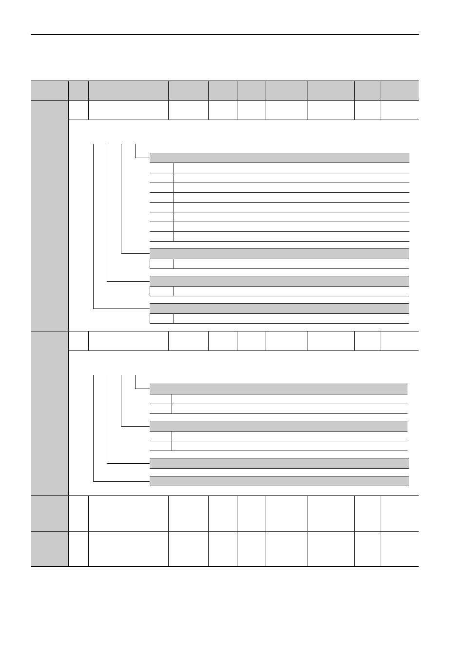
Pn81E
2
Input Signal Monitor
Selection
–
–
0000
Immediately
Setup
M2
*6
–
Pn81F
2
Command Data Alloca-
tion
–
–
0010
After restart
Setup
M2
*6
*1
Pn820
4
Forward Latching Allow-
able Area
-2147483648
to
2147483647
1
refer-
ence
unit
0
Immediately
Setup
–
*1
Pn822
4
Reverse Latching Allow-
able Area
-2147483648
to
2147483647
1
refer-
ence
unit
0
Immediately
Setup
–
*1
∗1.
For details, refer to
Σ
-V Series User’s Manual MECHATROLINK-III Standard Servo Profile Commands
(Manual
No.: SIEP S800000 63).
∗6.
This parameter is enabled only for MECHATROLINK-II-compatible profile.
(cont’d)
Parameter
No.
Size
Name
Setting
Range
Units
Factory
Setting
When
Enabled
Classification Profile Reference
Section
4th 3rd 2nd 1st
digit digit digit digit
n.
IO12 Signal Mapping
0
No mapping
1
Monitors CN1-13 input terminal.
2
Monitors CN1-7 input terminal.
3
Monitors CN1-8 input terminal.
4
Monitors CN1-9 input terminal.
5
Monitors CN1-10 input terminal.
6
Monitors CN1-11 input terminal.
7
Monitors CN1-12 input terminal.
IO13 Signal Mapping
0 to 7
Same as IO2 signal mapping.
IO14 Signal Mapping
0 to 7
Same as IO2 signal mapping.
IO15 Signal Mapping
0 to 7
Same as IO2 signal mapping.
4th 3rd 2nd 1st
digit digit digit digit
n.
Option Field Allocation
0
Disables OPTION bit allocation.
1
Enables OPTION bit allocation.
Software Limit Function
0
Disables allocation.
1
Enables allocation.
Reserved (Do not change.)
Reserved (Do not change.)