1) wiring example, Mecha – Yaskawa Σ-V Series AC Servo Drives Rotational Motor MECHATROLINK-III User Manual
Page 76
4.3 Basic Functions Settings
4-11
4
Op
er
at
io
n
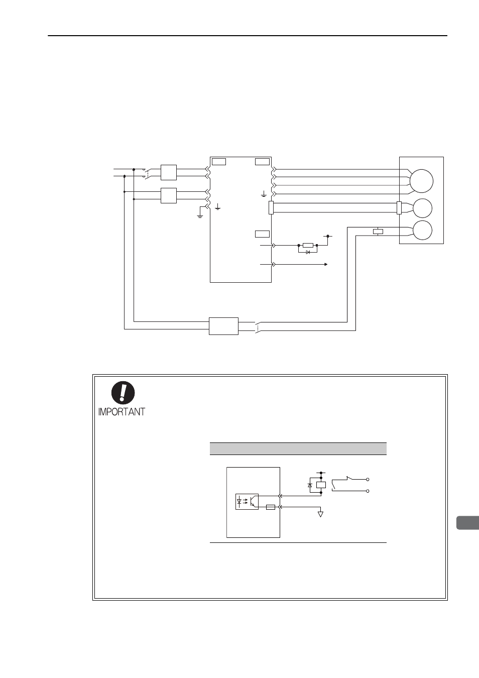
(1) Wiring Example
Use the brake signal (/BK) and the brake power supply to form a brake ON/OFF circuit. The following dia-
gram shows a standard wiring example.
The timing can be easily set using the brake signal (/BK).
• Always connect a surge absorber.
Recommended surge absorber: Z15D151 (manufactured by SEMITEC Corporation)
• After the surge absorber is connected, check the total time the brake is applied for the
system. Depending on the surge absorber, the total time the brake is applied can be
changed.
• Configure the relay circuit to apply the holding brake by the emergency stop.
• The allocation of the /BK signal can be changed. Refer to
(3) Brake Signal (/BK) Allo-
cation
to set the parameter Pn50F.
• Always separate the 24-VDC power supply for the 24-V brake from other power sup-
plies, such as the control or I/O signal (CN1) power supplies. If the power supply is
shared, the I/O signals might malfunction.
M
BK
ENC
U
V
W
5
11
CN2
BK-RY
BK-RY
+24V
L1
L2
C1
C2
/BK
COM_SG
CN1
CN3
CN4
1D
0 V
BK-RY: Brake control relay
Brake power supply for 24 VDC is not included.
Servomotor
with holding
brake
Surge
absorber
SERVOPACK
Power supply
Non-isolated
AC/DC converter
for main power supply
Non-isolated
AC/DC converter
for control
power supply
Brake power
supply
MECHA
Relay Circuit Example
0 V
Emergency stop
5 to 24 VDC
SERVOPACK
Photocoupler