6 using more than one servopack, 1) wiring example, 2) precautions – Yaskawa Σ-V Series AC Servo Drives Rotational Motor MECHATROLINK-III User Manual
Page 43: Mecha
3 Wiring and Connection
3.1.6 Using More Than One SERVOPACK
3-6
3.1.6
Using More Than One SERVOPACK
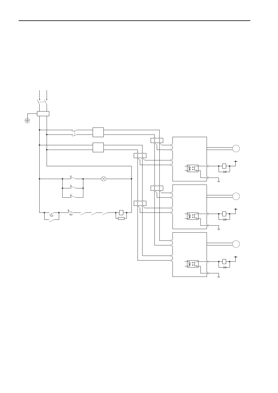
This section shows an example of the wiring and the precautions when more than one SERVOPACK is used.
(1) Wiring Example
The alarm output (ALM) of each SERVOPACK operates a separate alarm detection relay (1Ry, 2Ry or 3Ry).
When the alarm occurs, the ALM output signal transistor is turned OFF.
(2) Precautions
• Multiple SERVOPACKs can share a single molded-case circuit breaker (1QF) or noise filter. Always select
a molded-case circuit breaker or noise filter that has enough capacity for the total power supply capacity
(load conditions) of the SERVOPACKs.
• The same ground, COM_SG, is used for all four sequence output signals for a
Σ
-series SERVOPACK with a
DC power input. If the alarm outputs from the SERVOPACKs are connected in series, it will not be possible
to receive the output signals normally when an alarm occurs.
R
T
1QF
1FLT
1KM
1PL
1Ry
2Ry
3Ry
1Ry
2Ry
3Ry
1KM
1KM
1SA
CN3
L1
L2
C1
C2
CN1
4
5
COM_SG
ALM
1Ry
1D
0V
+24V
M
CN3
L1
L2
C1
C2
CN1
4
5
COM_SG
ALM
2Ry
2D
0V
+24V
M
CN3
L1
L2
C1
C2
CN1
4
5
COM_SG
ALM
3Ry
3D
0V
+24V
M
1QF
1FLT
1KM
1Ry
2Ry
3Ry
: Molded-case circuit breaker
: Noise filter
: Magnetic contactor (for main circuit power supply)
: Relay
: Relay
: Relay
1PL
1SA
1D
2D
3D
: Indicator lamp
: Surge absorber
: Flywheel diode
: Flywheel diode
: Flywheel diode
Non-isolated AC/DC converter
for main circuit power supply
Non-isolated AC/DC converter
for control power supply
Servomotor
Servomotor
Servomotor
supply ON
(For servo alarm display)
Main power
supply OFF
Main power
SERVOPACK
SERVOPACK
SERVOPACK
Relay
terminal
Relay
terminal
Relay
terminal
Relay
terminal
MECHA