2 example of i/o signal connections, Mecha – Yaskawa Σ-V Series AC Servo Drives Rotational Motor MECHATROLINK-III User Manual
Page 46
3.2 I/O Signal Connections
3-9
3
Wirin
g and
Co
nnectio
n
3.2.2
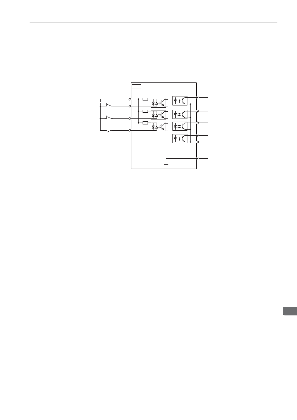
Example of I/O Signal Connections
The following diagram shows a typical connection example.
∗
The 24-VDC power supply is not included. Use a 24-VDC power supply with double insulation or reinforced insula-
tion.
Note: The functions allocated to the input signals /DEC, P-OT, N-OT and the output signals /SO1, /SO2, and /SO3 can be
changed by using the parameters. Refer to
3.3.1 Input Signal Allocations
and
3.3.2 Output Signal Allocations
.
/BK (SO1)
/SO2
/SO3
ALM
11
10
4
+24VIN
+24V
∗
3.3 k
Ω
2
8
7
P-OT
N-OT
/DEC
3
COM_SG
FG
9
5
1
CN1
SERVOPACK
Photocoupler output
Max. operating voltage: 30 VDC
Max. output current: 50 mA DC
Servo alarm output
(OFF for an alarm)
Brake
(Brake released when ON)
Reverse run prohibited
(Prohibited when OFF)
Forward run prohibited
(Prohibited when OFF)
Homing deceleration
switch
(Decelerated when ON)
Control power supply
for sequence signal
MECHA