5 wiring mechatrolink-iii communications, 5 wiring mechatrolink- iii communications, M-iii – Yaskawa Σ-V Series AC Servo Drives Rotational Motor MECHATROLINK-III User Manual
Page 59
3 Wiring and Connection
3-22
3.5
Wiring MECHATROLINK-
III
Communications
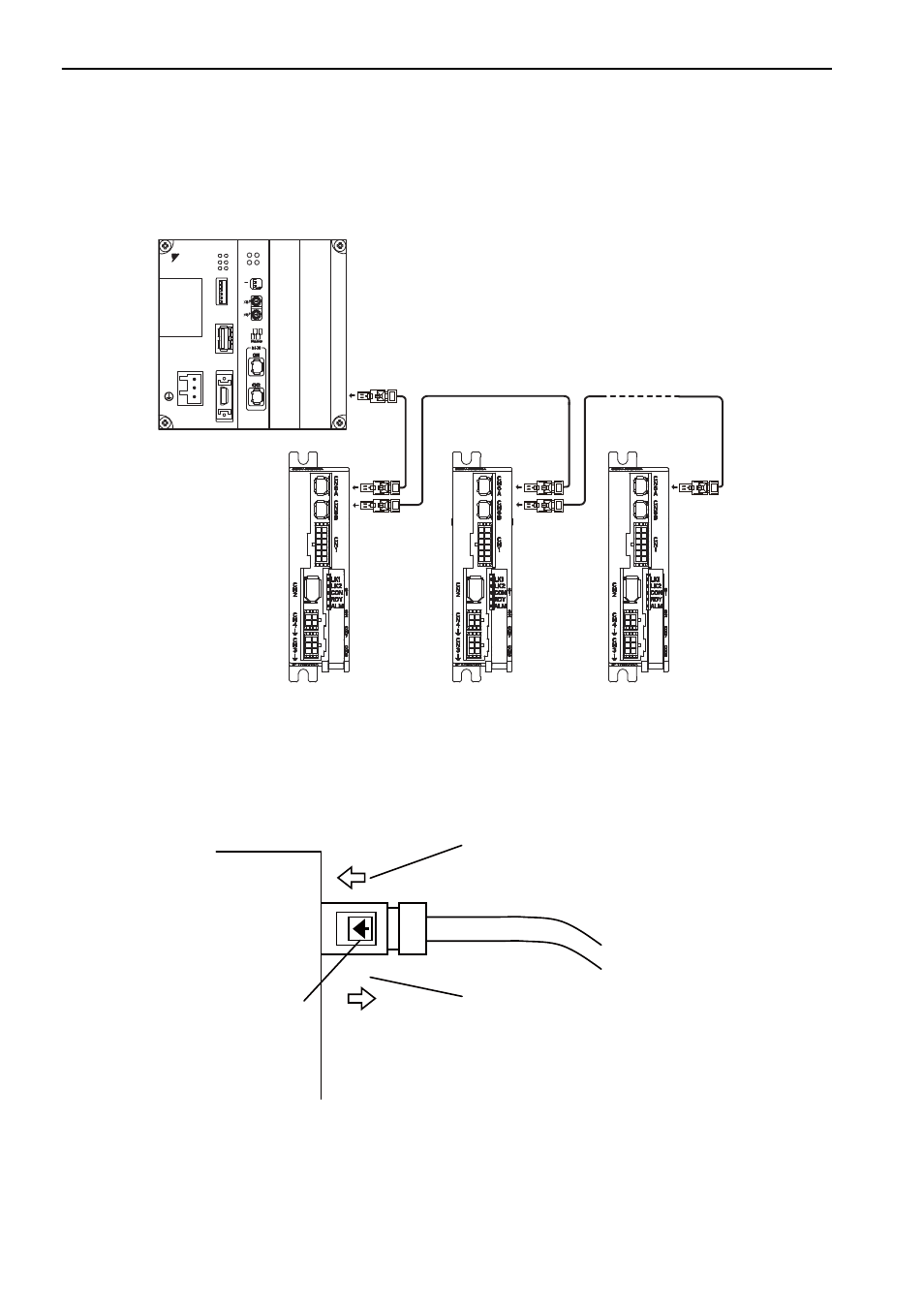
The following diagram shows an example of connections between a host controller and a SERVOPACK using.
MECHATROLINK-III communications cables (CN6A, CN6B).
Note: The length of the cable between stations (L1, L2 ... Ln) must be 50 m maximum.
For removing the MECHATROLINK-III communications cable connectors from the SERVOPACK, refer to the following
procedure.
Slide the lock injector of the connector to the SERVOPACK side to unlock and remove the MECHATROLINK-III com-
munications cable connectors.
Note: The MECHATROLINK-III communications cable connector may be damaged if it is removed without being
unlocking.
Ln
L1
L2
DC24V
DC 0V
MP2300
YASKAWA
TEST
ޓ
ޓ
ޓ
Option
Option
RDY
ALM
TX
RUN
ERR
BAT
MON
CNFG
INT
SUP
STOP
SW1
OFF
ON
BATTERY
CPU I/O
M-
I
/
II
SVC-01
ERR
LK2
RUN
LK1
M/S
ON
OFF
M-III
SERVOPACK
Lock injector
1. Slide the lock injector to
the SERVOPACK side.
2. Remove the connector while the lock
injector is slid to the SERVOPACK
side.
M-III