Mecha – Yaskawa Σ-V Series AC Servo Drives Rotational Motor MECHATROLINK-III User Manual
Page 299
9.1 List of Parameters
9-17
9
Ap
pend
ix
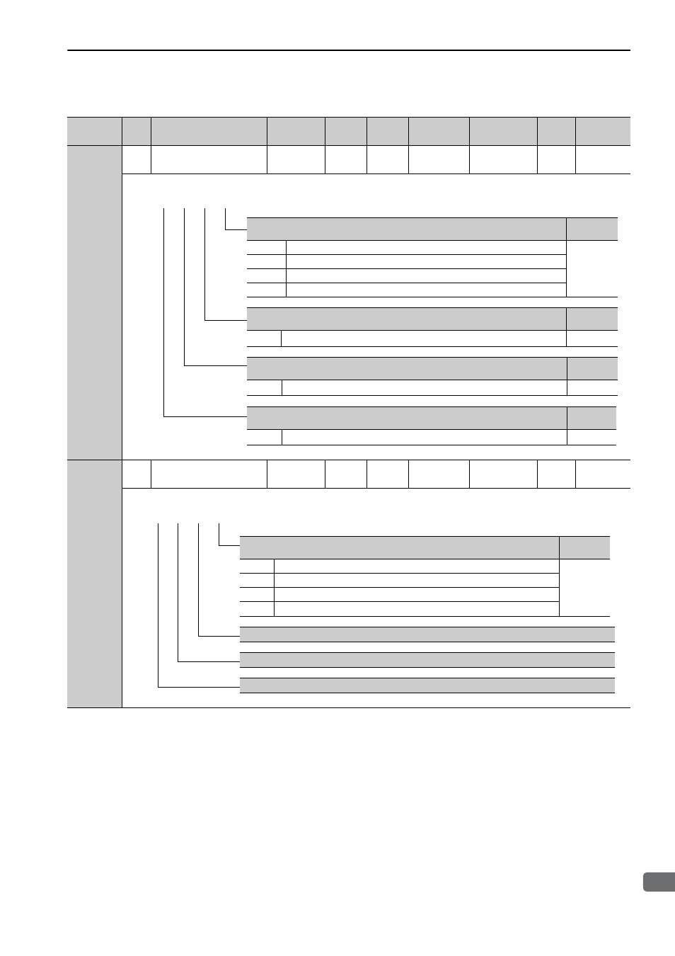
Pn50F
2
Output Signal Selection 2
0000 to
3333
−
0100
After restart
Setup
−
−
Pn510
2
Output Signal Selection 3
0000 to
0333
−
0000
After restart
Setup
−
−
(cont’d)
Parameter
No.
Size
Name
Setting
Range
Units
Factory
Setting
When
Enabled
Classification Profile Reference
Section
Torque Limit Detection Signal Mapping (/CLT)
Reference
Section
0
Disabled (the above signal is not used.)
4.6.3
1
Outputs the signal from CN1-11 output terminal.
2
Outputs the signal from CN1-10 output terminal.
3
Outputs the signal from CN1-9 output terminal.
Speed Limit Detection Signal Mapping (/VLT)
Reference
Section
0 to 3
Same as /CLT Signal Mapping.
4.8.8
Brake Signal Mapping (/BK)
Reference
Section
0 to 3
Same as /CLT Signal Mapping.
4.3.4
Warning Signal Mapping (/WARN)
Reference
Section
0 to 3
Same as /CLT Signal Mapping.
4.8.2
4th 3rd 2nd 1st
digit digit digit digit
n.
4th 3rd 2nd 1st
digit digit digit digit
n.
MECHA
Near Signal Mapping (/NEAR)
Reference
Section
0
Disabled (the above signal is not used.)
4.8.7
1
Outputs the signal from CN1-11 terminal.
2
Outputs the signal from CN1-10 terminal.
3
Outputs the signal from CN1-9 terminal.
Reserved (Do not change.)
Reserved (Do not change.)
Reserved (Do not change.)