Yaskawa Σ-V Series AC Servo Drives Rotational Motor MECHATROLINK-III User Manual
Page 300
9 Appendix
9.1.2 Parameters
9-18
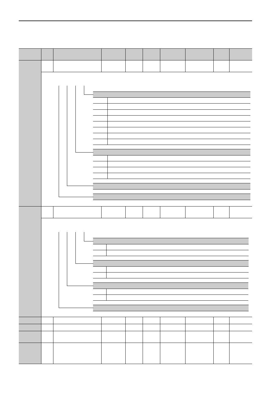
Pn511
2
Input Signal Selection 5
0000 to
FFFF
−
6580
After restart
Setup
−
3.3.1
Pn512
2
Output Signal Inverse Set-
ting
0000 to
0111
−
0000
After restart
Setup
−
3.3.2
Pn517
2
Reserved (Do not change.)
–
–
0000
–
–
–
–
Pn51B
4
Reserved (Do not change.)
–
–
1000
–
–
–
–
Pn51E
2
Excessive Position Error
Warning Level
10 to 100
1%
100
Immediately
Setup
–
8.2.1
Pn520
4
Excessive Position Error
Alarm Level
1 to
1073741823
1
refer-
ence
unit
5242880 Immediately
Setup
–
5.1.4,
8.1.1
(cont’d)
Parameter
No.
Size
Name
Setting
Range
Units
Factory
Setting
When
Enabled
Classification Profile Reference
Section
Homing Deceleration Switch Signal Mapping (/DEC)
0
Inputs the signal from CN1-7 input terminal.
1
Inputs the signal from CN1-3 input terminal.
2 to 6
Inputs the signal from CN1-8 input terminal.
7
Always active (fixed).
8
Not active (fixed).
9
Inputs the reversal signal from CN1-7 input terminal.
A
Inputs the reversal signal from CN1-3 input terminal.
B to F
Inputs the reversal signal from CN1-8 input terminal.
External Latch Signal Mapping (/EXT1)
0 to 6
Inputs the reversal signal from CN1-7 input terminal.
7
Always active (fixed).
8
Not active (fixed).
9 to F
Inputs the signal from CN1-7 input terminal.
Reserved (Do not change.)
Reserved (Do not change.)
4th 3rd 2nd 1st
digit digit digit digit
n.
Output Signal Inversion for CN1-11 Terminal
0
Does not inverse outputs.
1
Inverses outputs.
Output Signal Inversion for CN1-10 Terminal
0
Does not inverse outputs.
1
Inverses outputs.
Output Signal Inversion for CN1-9 Terminal
0
Does not inverse outputs.
1
Inverses outputs.
Reserved (Do not change.)
4th 3rd 2nd 1st
digit digit digit digit
n.