Power on the l10 raid chassis, Setting up the l10 raid chassis, Primary expansion 1 expansion 2 – Grass Valley K2 Storage System Instruction Manual v.3.3 User Manual
Page 55: Sas cables
June 25, 2009
K2 Storage System Instruction Manual
55
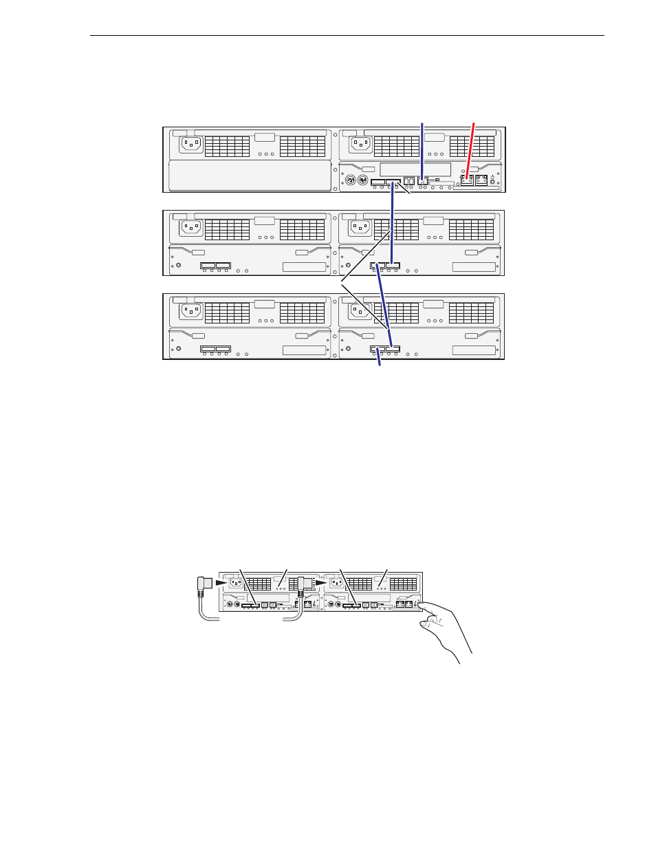
Setting up the L10 RAID chassis
If you have more Expansion chassis than those illustrated, continue the indicated
cabling pattern, connecting additional chassis to DP0.
Power on the L10 RAID chassis
Connect power cords and power up RAID storage devices as follows:
1. Verify power and cabling.
2. Press and hold down the power button on the controller, as shown.
If the RAID chassis has two controllers, you can press the power button on either
controller. You do not need to press both power buttons.
Pressing the power button on a controller also powers on any connected Expansion
chassis. There are no power buttons on Expansion chassis.
3. Release the power button when the Power Good LED on the power supply is
illuminated. This takes 1-3 seconds.
FLT/LNK
FLT
RDY
DP-OUT
PS
FLT CLR
DP-IN
FLT/LNK
FLT
RDY
DP-OUT
PS
FLT CLR
DP-IN
FLT/LNK
FLT
RDY
DP-OUT
PS
FLT CLR
DP-IN
FLT/LNK
FLT
RDY
DP-OUT
PS
FLT CLR
DP-IN
BBU IN
MODEM
FLT/LNK
HPE
FLT
A/L
BACKUP
ACT/LNK
LNK/ACT
FLT
HP
5 4 3 2
RDY
LAN
BAT
MNT
ACS
MC
DP1
DP0
HP
1 0
BBU IN
MODEM
FLT/LNK
HPE
FLT
A/L
BACKUP
ACT/LNK
LNK/ACT
FLT
HP
5 4 3 2
RDY
LAN
BAT
MNT
ACS
MC
DP1
DP0
HP
1 0
Primary
Expansion 1
Expansion 2
To control port
on GigE switch
DP0
To
Expansion
3
To K2 Media
Server
SAS cable connectors are keyed to DP IN/OUT ports.
SAS cables
BBU IN
MODEM
FLT/LNK
HPE
FLT
A/L
BACKUP
ACT/LNK
LNK/ACT
FLT
HP
5 4 3 2
RDY
LAN
BAT
MNT
ACS
MC
DP1
DP0
HP
1 0
BBU IN
MODEM
FLT/LNK
HPE
FLT
A/L
BACKUP
ACT/LNK
LNK/ACT
FLT
HP
5 4 3 2
RDY
LAN
BAT
MNT
ACS
MC
DP1
DP0
HP
1 0
Power Cords
(115V/230V)
RDY
LED
RDY
LED
Power Good
LED
Power Good
LED