Setting up the l20r raid chassis, Chapter 5 installing the level 20r storage system, Primary expansion 1 expansion 2 – Grass Valley K2 Storage System Instruction Manual v.3.3 User Manual
Page 204: Dp0 controller 1 controller 0, Sas cables
204
K2 Storage System Instruction Manual
June 25, 2009
Chapter 5 Installing the Level 20R Storage System
Setting up the L20R RAID chassis
Do the following to prepare the L20R RAID storage devices:
• Install the chassis in its permanent location. After mounting the chassis in the rack,
you must secure brackets to the front rail to support the Grass Valley bezel. Refer
to the K2 Lx0 RAID Instruction Manual for rack mount instructions.
•
“Connect the L20R RAID Primary and Expansion chassis” on page 204
•
“Power on the L20R RAID chassis” on page 205
In addition, you will configure network settings, SNMP settings, and bind RAID
disks. These tasks are part of the K2 System Configuration application and Storage
Utility procedures later in this chapter.
On the L20R RAID, you do not need to manually set a Fibre Channel address ID on
controllers or a chassis address on Expansion chassis.
Once the RAID storage is connected and configured, do not swap Expansion chassis
or otherwise reconfigure storage. If you connect an Expansion chassis in a different
order or to the wrong controller, the controller will see a configuration mismatch and
fault.
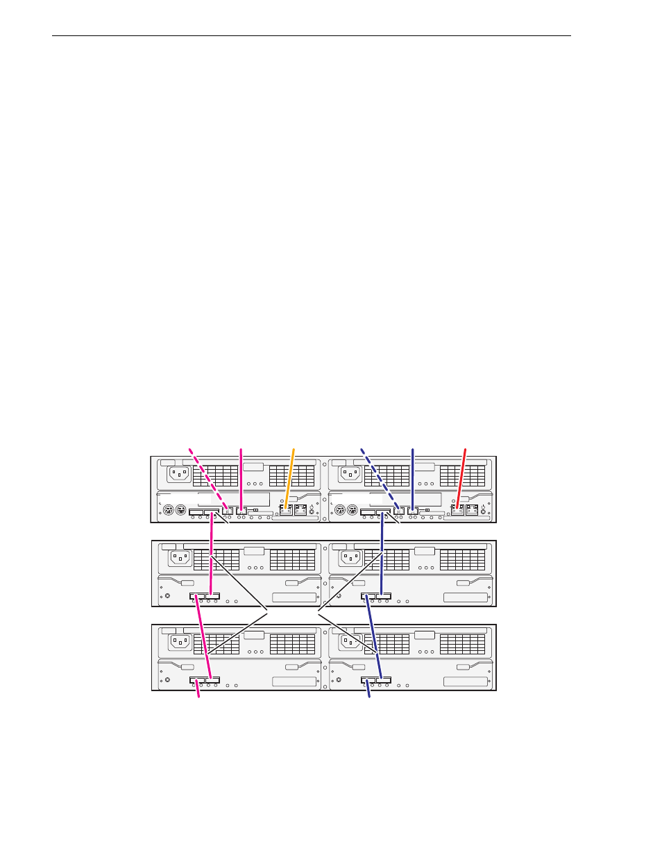
Connect the L20R RAID Primary and Expansion chassis
Connect Ethernet, Fibre Channel, and SAS cabling as shown.
If you have more Expansion chassis than those illustrated, continue the indicated
cabling pattern, connecting additional chassis to DP0.
FLT/LNK
FLT
RDY
DP-OUT
PS
FLT CLR
DP-IN
FLT/LNK
FLT
RDY
DP-OUT
PS
FLT CLR
DP-IN
FLT/LNK
FLT
RDY
DP-OUT
PS
FLT CLR
DP-IN
FLT/LNK
FLT
RDY
DP-OUT
PS
FLT CLR
DP-IN
BBU IN
MODEM
FLT/LNK
HPE
FLT
A/L
BACKUP
ACT/LNK
LNK/ACT
FLT
HP
5 4 3 2
RDY
LAN
BAT
MNT
ACS
MC
DP1
DP0
HP
1 0
BBU IN
MODEM
FLT/LNK
HPE
FLT
A/L
BACKUP
ACT/LNK
LNK/ACT
FLT
HP
5 4 3 2
RDY
LAN
BAT
MNT
ACS
MC
DP1
DP0
HP
1 0
Primary
Expansion 1
Expansion 2
DP0
To K2 Media
Server A
To K2 Media
Server B
To NH server
(optional)
To NH server
(optional)
To control port
on GigE switch A
To control port
on GigE switch B
DP0
Controller 1
Controller 0
To
Expansion
3
To
Expansion
3
SAS cable connectors are keyed
to DP IN/OUT ports.
SAS cables