Chapter 2: functional overview, 1 functional block diagram – ElmoMC Multi-Axis Motion Controller-Maestro User Manual
Page 15
Maestro
Software Manual
MAN-MASSW (Ver. Q)
2-1
Chapter 2: Functional Overview
This chapter takes a look at the organization of
Maestro
software.
2.1
Functional Block Diagram
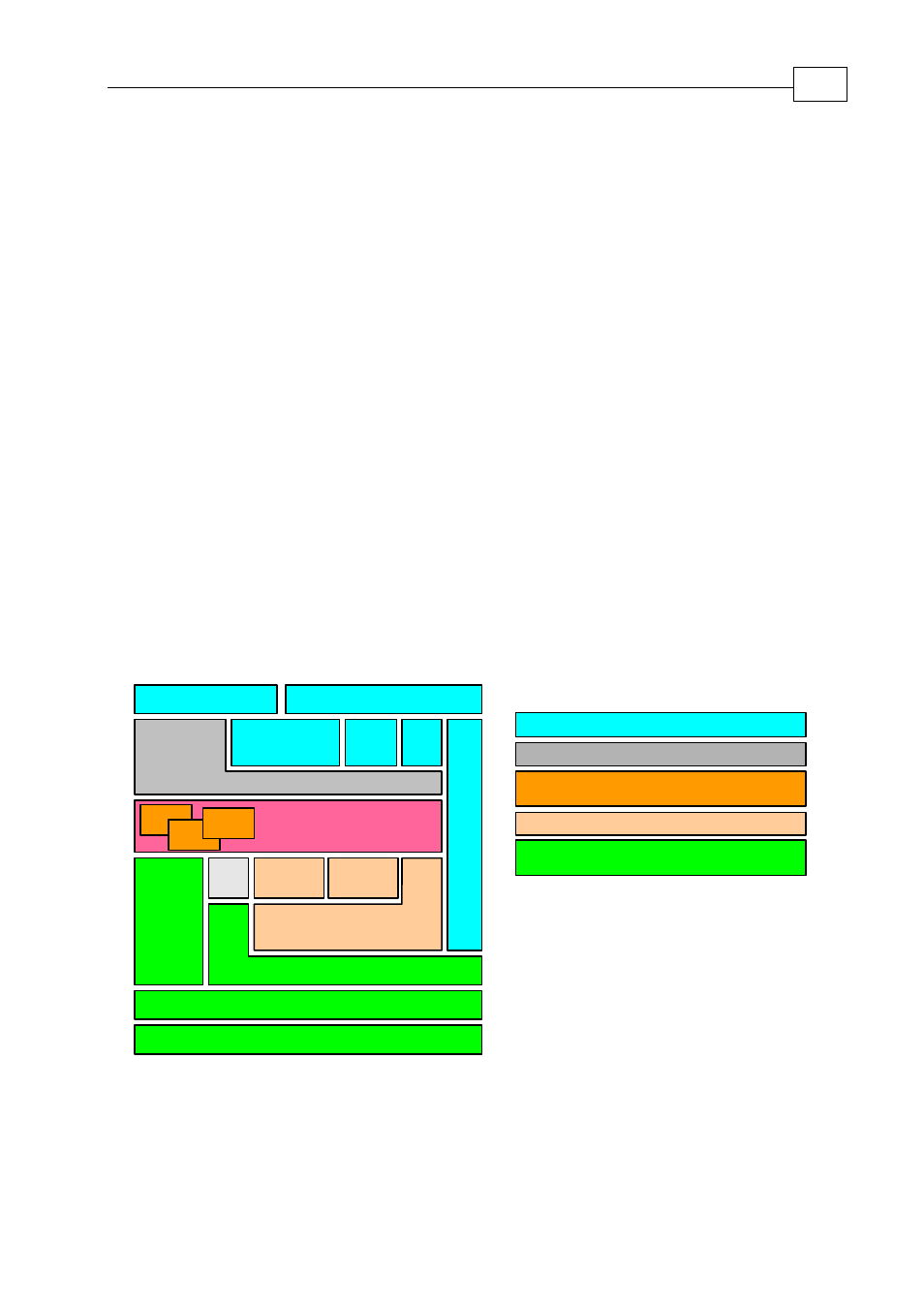
The Maestro’s functionality can be organized into the 5 groups shown below.
The first group (Host Communications Services) contains the standard interfaces and
protocols that enable the
Maestro
to communicates with the “outside world”.
The Command Line Interpreter is a utility that enables individual commands to be executed
immediately by either the
Maestro
or by a
SimplIQ
drive on a specified axis.
The Kernel is the part of the Maestro that executes user programs.
The Motion Manager sends commands and information to all axes and receives
information so that it can coordinate motion between all the axes.
The Maestro is designed to manage multiple axes on a CAN Open network. The CAN
Network Communication Server contains the CAN Open interfaces and protocols that
enable the
Maestro
to do so.
Kernel
Vector
Axis Manager
CAN
Bus
Services
Ga
te
w
a
y
Ethernet
RS - 232
WEB
TelNet
Host
API
I/O
CANopen Master
CANopen API
Key:
Host Communication Services
Command Line Interpeter
Virtual Machines
(for executing User Programs)
Motion Manager
CAN Network
Communications Server
Virtual
Machine
Command Line Interpeter
CANopen (DS-301)
Group
Virtual
Machine
Virtual
Machine
Figure
2-1 The
Maestro's
Building Block