I2c bus, Keyboard / display interface, C bus – Teledyne 9110EH - Nitrogen Oxides Analyzer User Manual
Page 225: Table 11-4, Dc power supply acceptable levels
Model 9110EH Instruction Manual Troubleshooting & Repair
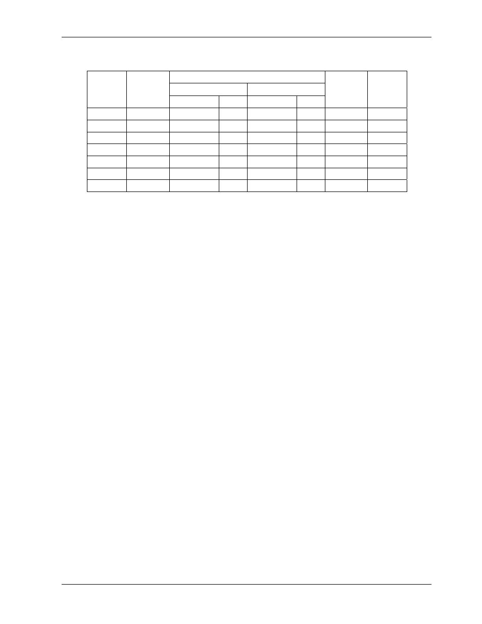
Table 11-4: DC Power Supply Acceptable Levels
CHECK relay board Test Points
From Test Point
To Test Point
Power
Supply
Voltage
Name # Name #
Min V
Max V
PS1 +5 DGND 1 +5 2
+4.80
+5.25
PS1 +15 AGND 3 +15 4
+13.5
+16.0
PS1 -15 AGND 3 -15V 5
-14.0
-16.0
PS1 AGND AGND 3 DGND 1 -0.05 +0.05
PS1 Chassis DGND 1 Chassis N/A -0.05 +0.05
PS2 +12
+12V
Ret
6 +12V 7
+11.8
+12.5
PS2 DGND
+12V
Ret 6 DGND 1 -0.05 +0.05
11.5.6. I
2
C Bus
Operation of the I
2
C bus can be verified by observing the behavior of the LED labeled D1 on
the relay board in conjunction with the performance of the front panel display. Assuming
that the DC power supplies are operating properly and the wiring from the motherboard to
the keyboard as well as from the keyboard to the relay board is intact, the I
2
C bus is
operating properly if:
• D1 on the relay board is flashing or
• D1 is not flashing but pressing a key on the front panel results in a change to the
display.
If the display is locked up or if the analyzer is not booting up at all, the I
2
C bus may be the
cause. Contact customer service if you suspect a problem with the I
2
C bus.
11.5.7. Keyboard / Display Interface
The front panel keyboard, the display and the keyboard/display circuit board can be verified
by observing the operation of the display when power is applied to the instrument and when
a key is pressed on the front panel. Assuming that there are no wiring problems and that
the DC power supplies are operating properly:
• The vacuum fluorescence display is working properly if, on power-up, a “-“ character
is visible on the upper left hand corner of the display.
• If there is no “-“ character on the display at power-up but the D1 LED on the relay
board is flashing, the keyboard/display circuit may be bad.
• If the analyzer starts operation with a normal display but pressing a key on the front
panel does not change the display, then there are three possible problems:
• One or more of the keys is bad,
• The interrupt signal between the keyboard and the motherboard is broken or
• The keyboard circuit is bad.
You can verify this failure by logging on to the instrument using APICOM or a terminal
program. If the analyzer responds to remote commands and the display changes accord-
ingly, the display wiring or the I
2
C bus may be faulty.
M9110EH Rev 0
211