Keypad, Front panel states led’s, Display / keyboard interface electronics – Teledyne 9110EH - Nitrogen Oxides Analyzer User Manual
Page 202: Table 10-4, Front panel status led’s
Theory of Operation Model 9110EH Instruction Manual
ment calibration or certain diagnostic procedures, the instrument’s response messages are
also displayed here.
Concentration Field: The far right portion of the top line of text displays the concentration of
the sample gas currently being measured by the analyzer. The number reported here is the
actual concentration of the sample gas reported in whatever units the user selects
(Section 6.5.6). This number remains unaffected, regardless of how the ranges of the
instrument’s analog outputs are configured.
Key Definition Field: The bottom line of text displays is reserved for defining the test
function of the row of keys just below the display. These definitions change depending on
which part of the software menu tree is currently being displayed.
10.3.7.3. Keypad
The row of eight keys just below the vacuum florescent display are the main method by
which the user interacts with the analyzer. These keys are context sensitive and are
dynamically re-defined as the user moves around in the software menu structure.
10.3.7.4. Front Panel States LED’s
There are three status LED’s located in the upper right corner of the M9110EH’s front panel:
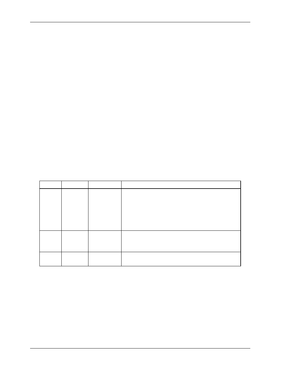
Table 10-4: Front Panel Status LED’s
Name Color
State
Definition
SAMPLE Green
Off
On
Blinking
Unit is not operating in sample mode, iDAS is
disabled.
Unit is operating in Sample Mode, Front Panel
Display being updated, iDAS data being stored.
Unit is operating in sample mode, front panel display
being updated, iDAS hold-off mode is ON, iDAS
disabled
CAL Yellow Off
On
Blinking
Auto Cal disabled
Auto Cal enabled
Unit is in calibration mode
FAULT Red
Off
Blinking
No warning exists
Warning(s) exist
10.3.7.5. Display / Keyboard Interface Electronics
The display of the analyzer is a vacuum fluorescence display with two lines of 40 text
characters each. Information is organized as shown in Figure 3-2. Figure 10-17 shows the
electronic diagram of the display / keyboard circuitry.
Through the keyboard/display interface electronics, the M9110EH Analyzer captures the status
of the eight front panel keys, alerts the CPU when keys are depressed and manages
communications between the keyboard, the CPU and the front panel display. Except for the
keyboard interrupt status bit, all communication between the CPU and the keyboard/display
is handle by the instrument’s I
2
C bus. The CPU controls the clock signal and determines
when the various devices on the bus are allowed to talk or required to listen. Data packets
are labeled with addresses that identify for which device the information is intended.
188 M9110EH Rev 0