Functional description, Table 420 faceplate led – Nortel Networks Circuit Card 311 User Manual
Page 992
992
NTBK51 Downloadable D-channel Handler daughterboard
One NTBK51 daughterboard is required for each PRI link.
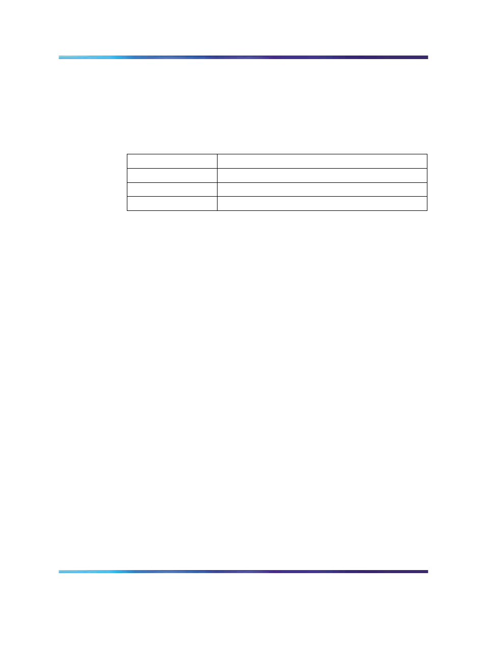
LEDs are located on the faceplate of the NTAK09/NTBK50 card. The
DCHI LED is a dual-color (red/green). The LED is described in
Table 420
Faceplate LED
State
Definition
On (Red)
NTBK51 is disabled.
On (Green)
NTBK51 is enabled, but not necessarily established.
Off
NTBK51 is not equipped.
Functional description
The main functional blocks of the NTBK51 architecture include the following:
•
Microprocessors
•
Main memory
•
Shared memory
•
EPROM memory
•
Flash EPROM memory
•
EEPROM memory
•
Serial communication controller
•
Sanity timer
•
Bus timer
The main functional blocks of the NTBK51 architecture include the following:
•
Microprocessors
•
Main memory
•
Shared memory
•
EPROM memory
•
Flash EPROM memory
•
EEPROM memory
•
Serial communication controller
•
Sanity timer
•
Bus timer
Nortel Communication Server 1000
Circuit Card Reference
NN43001-311
01.04
Standard
Release 5.0
23 May 2008
Copyright © 2003-2008, Nortel Networks
.