Figure 300 ntrb21 tmdi card with clock controller, Table 432 ntrb21 led states, Figure 300 – Nortel Networks Circuit Card 311 User Manual
Page 1056
1056
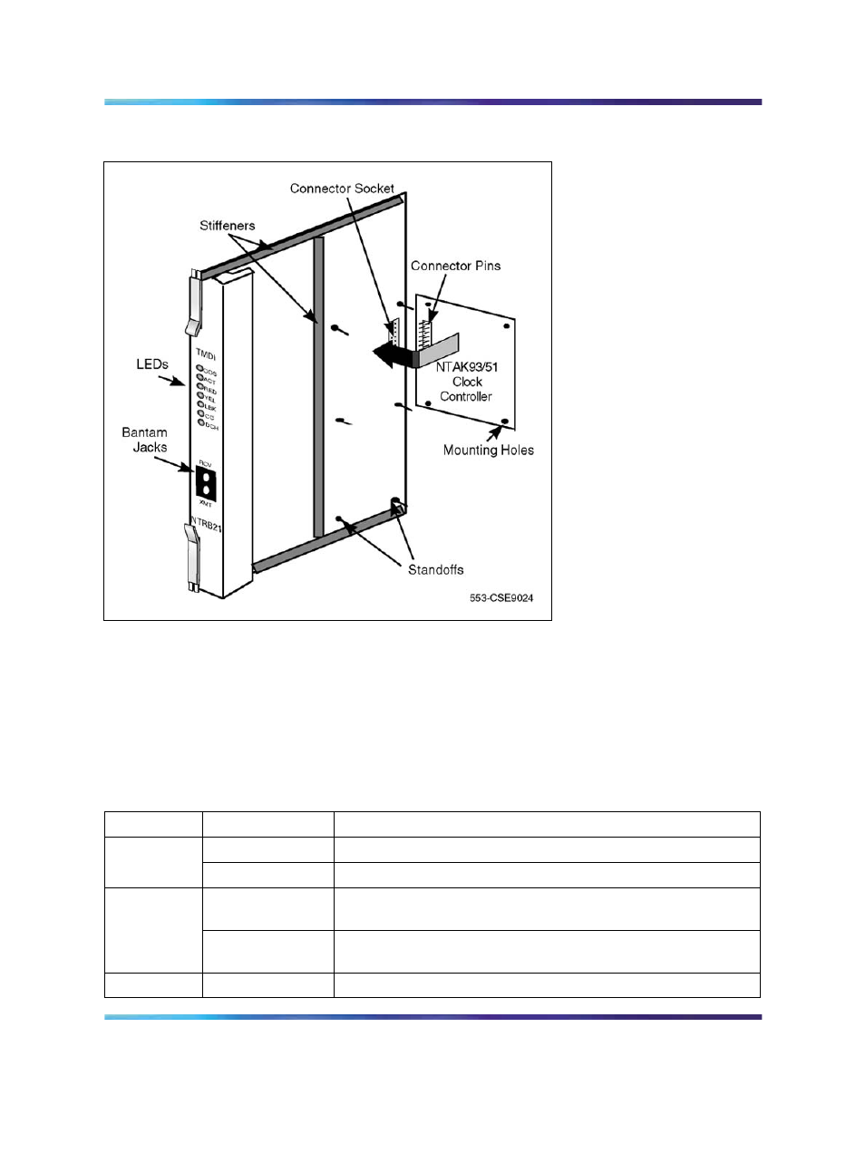
NTRB21 DTI/PRI/DCH TMDI card
Figure 300
NTRB21 TMDI card with clock controller
In general, the first five LEDs operate as follows:
•
During system power up, the LEDs are on.
•
When the self-test is in progress, the LEDs flash on and off three times,
then go into their appropriate states, as shown in
Table 432
NTRB21 LED states
LED
State
Definition
DIS
On (Red)
The NTRB21 circuit card is disabled.
Off
The NTRB21 is not in a disabled state.
ACT
On (Green)
The NTRB21 circuit card is in an active state. No alarm states
exist, the card is not disabled, nor is it in a loopback state.
Off
An alarm state or loopback state exists, or the card has been
disabled. See the other faceplate LEDs for more information.
RED
On (Red)
A red-alarm state has been detected.
Nortel Communication Server 1000
Circuit Card Reference
NN43001-311
01.04
Standard
Release 5.0
23 May 2008
Copyright © 2003-2008, Nortel Networks
.