Table 14 general purpose switch settings – Nortel Networks Circuit Card 311 User Manual
Page 85
NT5D12 Dual DTI/PRI (DDP) card
85
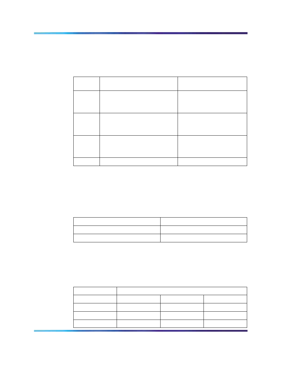
General purpose switches
Use switch set SW9 for Trunk 0; use switch set SW15 for Trunk 1 (see
14 "General purpose switch settings" (page 85)
).
Table 14
General purpose switch settings
Switch
Description
SW9/SW15
switch setting
1
Framing Mode
off - ESF
on - SF
2
Yellow Alarm Method
off - FDL
on - Digit2
3
Zero Code Suppression Mode
off - B8ZS
on - AMI
4
Unused
off
Trunk interface switches
A switch provides selection of T1 transmission. Use switch SW4 for Trunk 0;
use switch SW10 for Trunk 1 (see
Table 15 "Trunk interface transmission
mode switch settings" (page 85)
).
Table 15
Trunk interface transmission mode switch settings
Description
SW4/SW10 switch setting
For future use
off
T1
on
A set of three switches provides selection of dB values. Use SW5, SW6,
and SW7 for Trunk 0; use SW11, SW12, and SW13 for Trunk 1 (see
16 "Trunk interface line build out switch settings" (page 85)
Table 16
Trunk interface line build out switch settings
Switch Setting
Description
SW5/SW11
SW6/SW12
SW7/SW13
0 dB
off
off
off
7.5 dB
on
on
off
15 dB
on
off
on
Nortel Communication Server 1000
Circuit Card Reference
NN43001-311
01.04
Standard
Release 5.0
23 May 2008
Copyright © 2003-2008, Nortel Networks
.