Table 337 switch settings, Table 338 jumper settings – Nortel Networks Circuit Card 311 User Manual
Page 850
850
NTAK02 SDI/DCH card
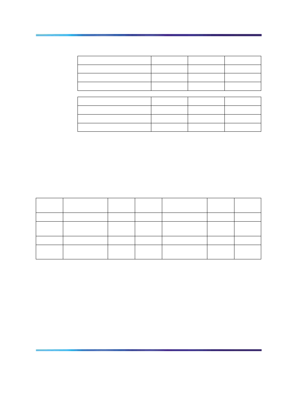
Table 337
Switch settings
Port 0
Port 1
SW 1-1
SW 1-2
SDI (not supported)
DCH
OFF
OFF
SDI (not supported)
DCH
OFF
ON
—
ESDI
ON
ON
Port 2
Port 3
SW 1-3
SW 1-4
SDI (not supported)
DCH
OFF
OFF
SDI (not supported)
DCH
OFF
ON
—
ESDI
ON
ON
Note: Digital Private Network Signaling System DPNSS can replace
the DCH function in the U.K.
Two ports offer the option for DTE/DCE configuration. This option is
selected from a jumper on the card.
Table 338 "Jumper settings" (page
shows the jumper settings.
Table 338
Jumper settings
Port
Jumper
location
Strap for
DTE
Strap for
DCE
Jumper
location
RS422
RS232
0
J10
C - B
B - A
1
J7 J6
C - B
C - B
B - A
B - A
J9
J8
C - B
C - B
B - A
B - A
2
J5
C - B
B - A
3
J4
J3
C - B
C - B
B - A
B - A
J2
J1
C - B
C - B
B - A
B - A
Connecting to the ports
External devices are connected to the SDI/DCH card by the following:
•
the NTAK19FB four-port SDI cable. This cable does not have to be
terminated at the cross connect terminal since it is equipped with
connectors.
•
the NE-A25-B cable. Terminate the NE-A25-B cable at the cross
connect terminal. Tables
Table 339 "NTAK02 pinouts - Port 0 at the
cross-connect terminal" (page 851)
through
connections at the cross-connect terminal - Port 3" (page 852)
give
the pinouts for the SDI/DCH card.
Nortel Communication Server 1000
Circuit Card Reference
NN43001-311
01.04
Standard
Release 5.0
23 May 2008
Copyright © 2003-2008, Nortel Networks
.