Table 412 carrier shield grounding switch settings, Table 413 carrier shield grounding switch settings, Table 414 carrier shield grounding switch settings – Nortel Networks Circuit Card 311 User Manual
Page 982
982
NTBK50 2.0 Mb PRI card
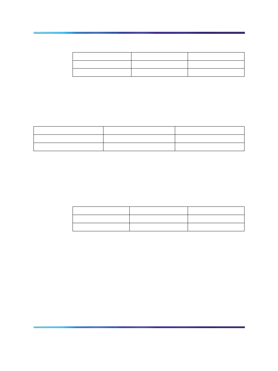
Table 412
Carrier Shield grounding switch settings
Switch
Down (On)
Up (Off)
SW 4 – 1
Rx – FGND
Rx – OPEN
SW 4 – 2
Tx – FGND
Tx – OPEN
Note: The usual method is to ground the outer conductor of the receive
coax signal.
Settings are shown in the Table below.
Table 413
Carrier shield grounding switch settings
Switch
Down (On)
Up (Off)
SW 4-1
Rx—FGND
Rx—OPEN
SW 4-2
Tx—FGND
Tx—OPEN
Note: The usual method is to ground the outer conductor of the receive
coax signal.
Table 414 "Carrier Shield grounding switch settings" (page 982)
lists the
Carrier Shield ground switch settings.
Table 414
Carrier Shield grounding switch settings
Switch
Down (On)
Up (Off)
SW 4 – 1
Rx – FGND
Rx – OPEN
SW 4 – 2
Tx – FGND
Tx – OPEN
Note: The usual method is to ground the outer conductor of the receive
coax signal.
Receiver functions
The receiver extracts data and clock from an AMI (Alternate Mark Inversion)
coded signal and outputs clock and synchronized data. The receiver is
sensitive to signals over the entire range of cable lengths and requires
no equalization. The clock and data recovery meets or exceeds the jitter
specifications of the CCITT recommendation G.823 and the jitter attenuation
requirements of the CCITT recommendation G.742. This provides jitter
attenuation increasing from 0 dB to 60 dB over the frequency range from
about 6 Hz to 6 KHz.
Nortel Communication Server 1000
Circuit Card Reference
NN43001-311
01.04
Standard
Release 5.0
23 May 2008
Copyright © 2003-2008, Nortel Networks
.