Cabling the lineside t1 card – Nortel Networks Circuit Card 311 User Manual
Page 202
202
NT5D11 and NT5D14 Lineside T1 Interface cards
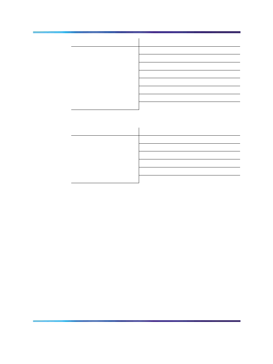
Available:
Motherboard/Daughterboard
0 and 1
1 and 2
4 and 5
7 and 8
8 and 9
9 and 10
12 and 13
13 and 14
The Lineside T1 card cannot be installed into the following card slot pairs:
Restricted:
Motherboard/Daughterboard
2 and 3
3 and 4
6 and 7
10 and 11
11 and 12
14 and 15
If the Lineside T1 card must be installed into one of the restricted card slot
pairs, rewire the IPE module card slot to the I/O panel by installing an
additional NT8D81 cable from the Lineside T1 card motherboard slot to
the I/O panel. Re-arrange the three backplane connectors for the affected
card slots. This permits the connection of the NT5D13AA Lineside T1 card
carrier and maintenance external I/O cable at the IPE module I/O panel
connector for card slots that are otherwise restricted.
Also, all Lineside T1 card connections can be made at the main distribution
frame instead of connecting the NT5D13 Lineside T1 card external I/O cable
at the I/O panel. This eliminates these card slots restrictions.
Cabling the Lineside T1 card
After configuring the dip switches and installing the Lineside T1 card into the
selected card slots, the Lineside T1 card is ready to be cabled to the CPE
or CSU equipment. Connections can also be made to the MMI terminal or
modem (optional), an external alarm (optional), and other Lineside T1 cards
for daisy-chain use of the MMI terminal (optional).
Nortel Communication Server 1000
Circuit Card Reference
NN43001-311
01.04
Standard
Release 5.0
23 May 2008
Copyright © 2003-2008, Nortel Networks
.