Figure 256 pad orientation, Table 306 pad switching algorithm, Table 306 "pad – Nortel Networks Circuit Card 311 User Manual
Page 791
Configuration
791
See
Table 306 "Pad switching algorithm" (page 791)
for the pad switching
control for the various through connections and the actual port-to-port loss
introduced for connections between the E and M Trunk card and any other
IPE port designated as Port B.
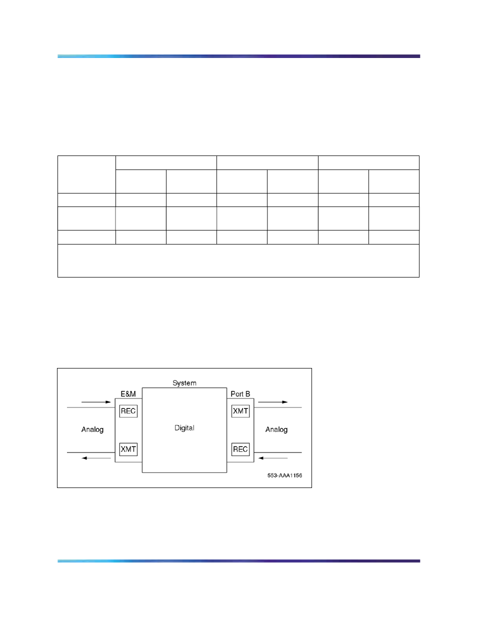
Figure 256 "Pad orientation" (page 791)
shows the pad switching orientation.
Table 306
Pad switching algorithm
Port B pads
E and M Trunk Pads
Port-to-port loss (dB)
Port B
Transmit
D to A
Receive
A to D
Transmit
D to A
Receive
A to D
Port B to
E and M
E and M to
Port B
IPE line
N/A
N/A
Out
In
2.5
3.5
Universal
trunk (TRC)
Out
Out
In
In
0
0
IPE TIE (VNL)
In
Out
In
Out
0
0
Note: Transmit and receive designations are from and to the system. Transmit is from the system to
the external facility (digital-to-analog direction in the E and M Trunk card). Receive is to the system
from the external facility (analog-to-digital direction in the E and M Trunk card).
Loss parameters are selected on the E and M trunk card by a switchable
pad controlled by Codec emulation software. For convenience in this
discussion, the pads settings are called "in" and "out." Pad settings are
determined by the three factors listed below: the first two are under direct
user control; the third is controlled indirectly.
Figure 256
Pad orientation
•
Class of service is assigned in LD 14.
•
Facility termination is selected (2-wire or 4-wire) in LD 14 (the 2-wire
setting provides 0.5 dB more loss in each direction of transmission for
echo control).
Nortel Communication Server 1000
Circuit Card Reference
NN43001-311
01.04
Standard
Release 5.0
23 May 2008
Copyright © 2003-2008, Nortel Networks
.