Table 452 connector j2 pin assignments, Shows the – Nortel Networks Circuit Card 311 User Manual
Page 1108
1108
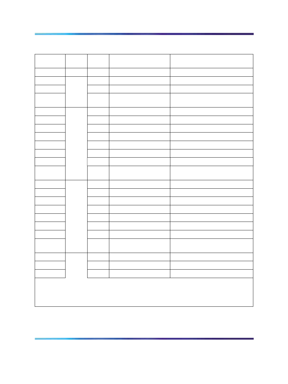
QPC841 Quad Serial Data Interface card
Table 452
Connector J2 pin assignments
Pin
Number
Port
Signal
Purpose in DTE mode
Purpose in DCE mode
1
FGD
Frame ground
Frame ground
2
TD
Transmitted data
Transmitted data
3
RD
Received data
Received data
4
RTS
Request to send (not
used)
Request to send (Note 2)
5
2
CTS
Clear to send (Note 1)
Clear to send
6
DSR
Data set ready (Note 1)
Data set ready
7
GND
Ground
Ground
8
CD
Carrier detect (Note 1)
Carrier detect (not Used)
20
DTR
Data terminal ready
Data terminal ready (Note 2))
9
TD
Transmitted data
Transmitted data
10
RD
Received data
Received data
11
RTS
Request to send (not
used)
Request to send (Note 2))
12
3
CTS
Clear to send (Note 1)
Clear to send
13
DSR
Data set ready (Note 1)
Data set ready
25
GND
Ground
Ground
24
CD
Carrier detect (Note 1)
Carrier detect (not used)
23
DTR
Data terminal ready
Data terminal ready (Note 2))
14
TD
Transmitted data
Transmitted data
15
RD
Received data
Received data
16
RTS
Request to send (not
used)
Request to send (Note 2))
17
4
CTS
Clear to send (Note 1)
Clear to send
18
DSR
Data set ready (Note 1)
Data set ready
19
GND
Ground
Ground
Note 1: In DTE mode, the signals CD, DSR, and CTS are tied to +12 volts (through a resistor) to
indicate that the QSDI port is always ready to transmit and receive data.
Note 2: In DCE mode, the signals DTR and RTS are tied to +12 volts (through a resistor) to indicate
that the QSDI port is always ready to transmit and receive data.
Nortel Communication Server 1000
Circuit Card Reference
NN43001-311
01.04
Standard
Release 5.0
23 May 2008
Copyright © 2003-2008, Nortel Networks
.