Figure 16 – Nortel Networks Circuit Card 311 User Manual
Page 68
68
Circuit card installation
Figure 16
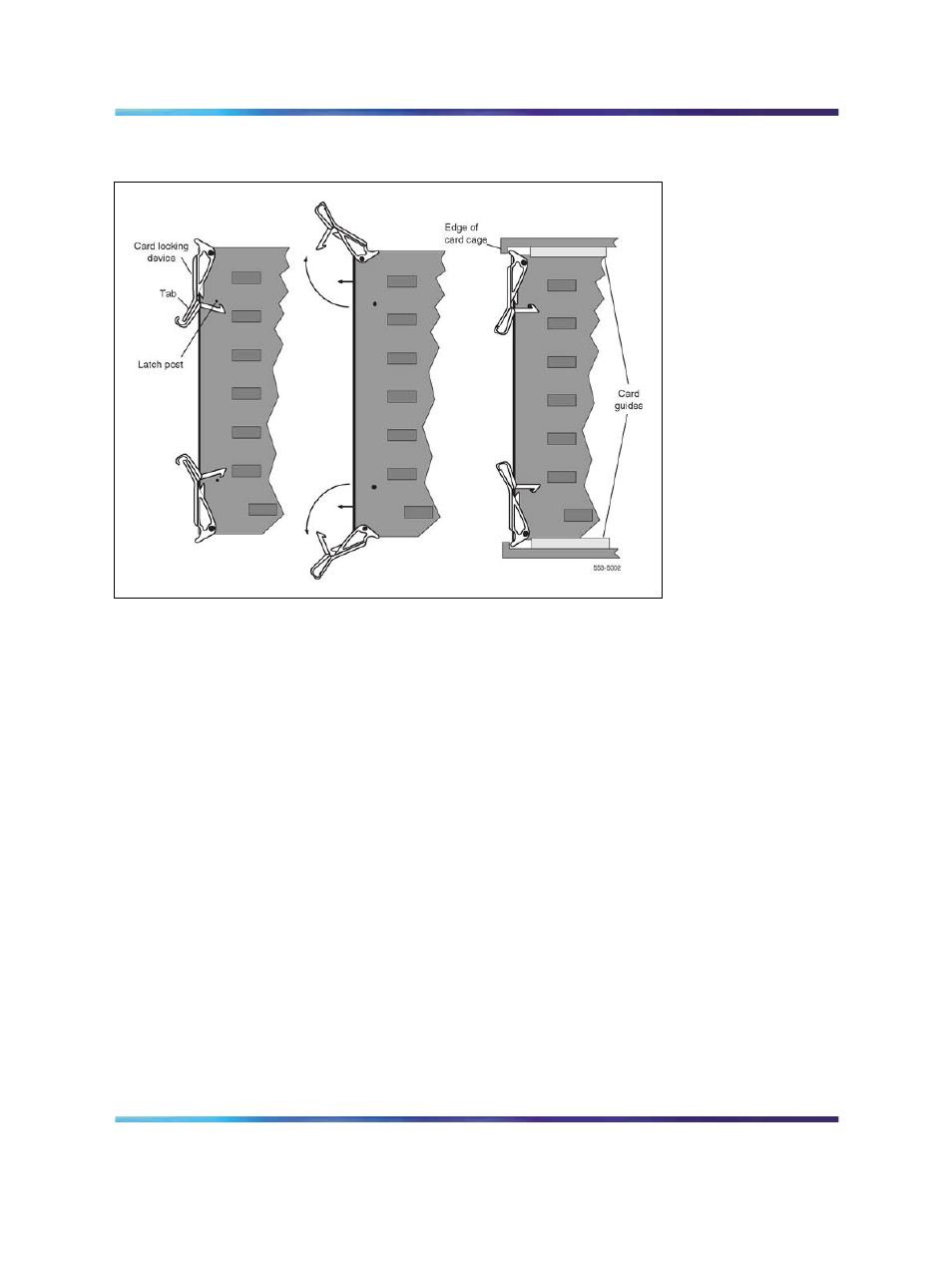
Installing the circuit card in the card cage
7
Insert the card into the card aligning guides in the card cage. Gently
push the card into the slot until you feel resistance. The tip of the
locking device must be behind the edge of the card cage (see
16 "Installing the circuit card in the card cage" (page 68)
).
8
Lock the card into position by simultaneously pushing the ends of
the locking devices against the faceplate.
Note: When IPE cards are installed, the red LED on the
faceplate remains lit for two to five seconds as a self-test runs.
If the self-test is completed successfully, the LED flashes three
times and remains lit until the card is configured and enabled
in software, then the LED goes out. If the LED does not follow
the pattern described or operates in any other manner (such as
continually flashing or remaining weakly lit), replace the card.
9
If there is an enable/disable switch, set it to Enb.
Note: Do not enable the switch on an NT8D04 Superloop
Network card or QPC414 Network card until network loop cables
are installed.
10
If you are adding a voice, conference, or tone and digit loop, press the
manual initialize (Man Int) button on the NT5D03 or the NT5D10 Call
Processor if the card is associated with the active Call Processor:
Nortel Communication Server 1000
Circuit Card Reference
NN43001-311
01.04
Standard
Release 5.0
23 May 2008
Copyright © 2003-2008, Nortel Networks
.