Table 122 lei card - lineside e1 i/o cable pinouts – Nortel Networks Circuit Card 311 User Manual
Page 284
284
NT5D33 and NT5D34 Lineside E1 Interface cards
Table 122
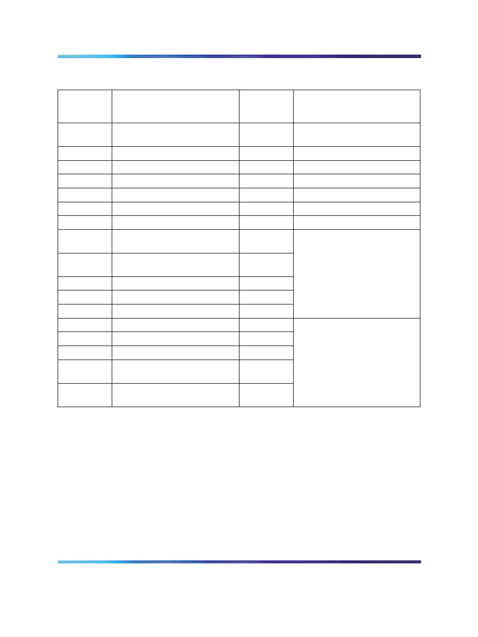
LEI card - lineside E1 I/O cable pinouts
I/O Panel
Connector
Pin
Lead Designations
LEI
Connector
Pin
LEI Cable Connector to
External
Equipment
1
E1 Tip Receive data
11
DB15 male to E1 (P2). LEI is CPE
transmit and receive to network
26
E1 Ring Receive data
3
2
E1 Tip Transmit data
1
27
E1 Ring Transmit data
9
3
Alarm out, common
1
28
Alarm out (normally open)
2
DB9 male to external alarm (P3)
4
Alarm out (normally closed)
3
7
Toward MMI terminal, receive
data
2
31
Toward MMI terminal, transmit
data
3
33
Ground
5
8
Control 1
7
32
Control 2
9
DB9 male toward MMI (P5).
Wired as DCE.
Data is transmitted on pin 2
(RXD) and received on pin 3
(TXD)
33
Ground
5
8
Control 1
7
32
Control 2
9
30
Away from MMI terminal, transmit
data
3
6
Away from MMI terminal, receive
data
2
DB9 female away from MMI
terminal (P4)
E1 Connections
For twisted-pair installations, E1 signaling for all 30 channels is transmitted
over P2 connector pins 1, 3, 9, and 11, as shown in
lineside E1 I/O cable pinouts" (page 284)
.
Plug the DB 15 male connector labeled "P2" into the E1 link. E1 transmit
and receive pairs must be turned over between the LEI and the CPE that is
hardwired without carrier facilities. If the LEI is connected through E1 carrier
facilities, the transmit and receive pairs must be wired straight through to the
RJ48 at the Telco demarc, the LTU, or other E1 carrier equipment. The E1
CPE at the far-end has transmit and receive wired straight from the RJ48
demarc at the far-end of the carrier facility.
Nortel Communication Server 1000
Circuit Card Reference
NN43001-311
01.04
Standard
Release 5.0
23 May 2008
Copyright © 2003-2008, Nortel Networks
.