Nortel Networks Circuit Card 311 User Manual
Page 343
Functional description
343
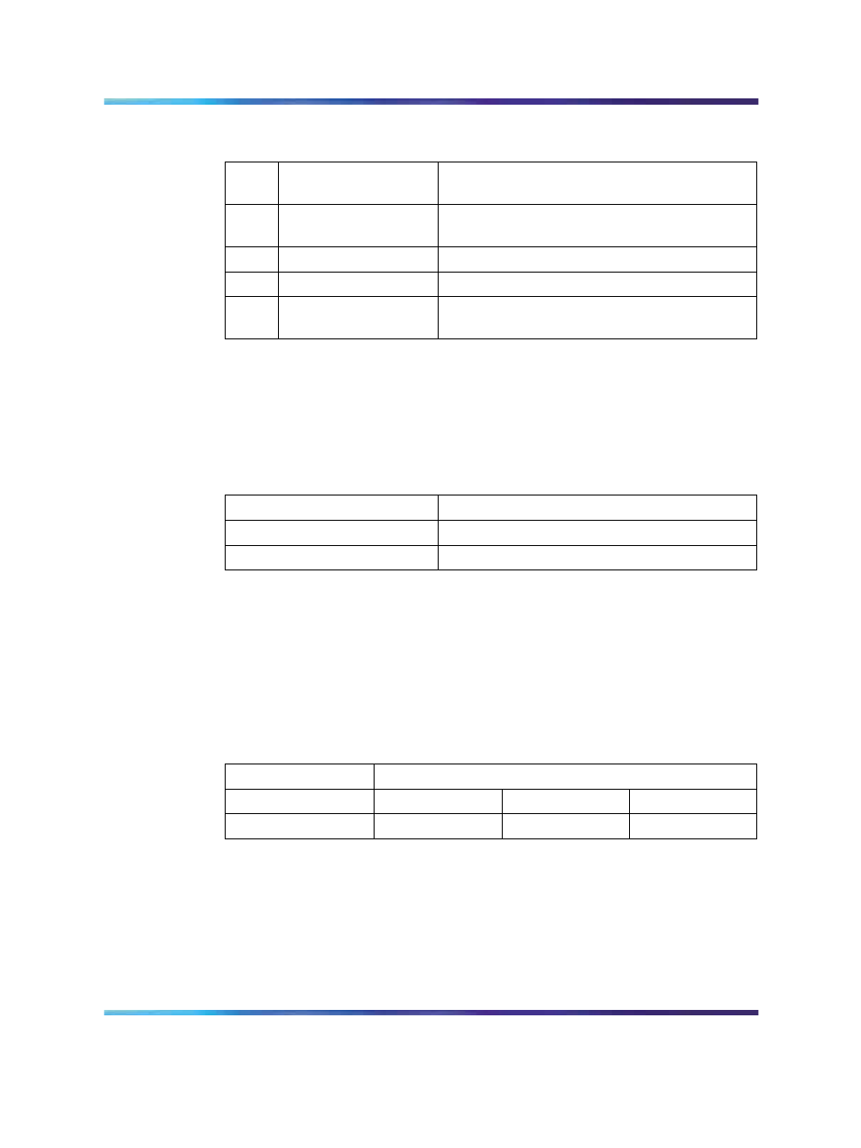
Table 144
Impedance level and loop mode switch settings
Swit
ch
Description
S9/S15 Switch Setting
1
Impedance level
OFF - 120 ohm
ON - 75 ohm
2
Spare
X
3
Spare
X
4
Unit mode
OFF - Loop operates in the DTI2 mode
ON - Loop operates in the PRI2 mode
Transmission mode
A per-trunk switch (S4/S10) provides selection of the digital trunk interface
type. Refer to
Table 145 "Impedance level and loop mode switch settings"
Table 145
Impedance level and loop mode switch settings
Description
S4/S10 switch settings
E1
OFF
Not used
Line build out
A per-trunk set of three switches (S5/S11, S6/S12 and S7/S13) provides
the dB value for the line build out. Refer to
Table 146 "Trunk interface line
build out switch settings" (page 343)
Note: Do not change this setup.
Table 146
Trunk interface line build out switch settings
Switch setting
Description
S5/S11
S6/S12
S7/S13
0dB
OFF
OFF
OFF
Receiver impedance
A per-trunk set of four DIP switches (S8/S14 provides selection between 75
or 120 ohm values. Refer to
Table 147 "Trunk interface impedance switch
.
Nortel Communication Server 1000
Circuit Card Reference
NN43001-311
01.04
Standard
Release 5.0
23 May 2008
Copyright © 2003-2008, Nortel Networks
.