Nortel Networks Circuit Card 311 User Manual
Page 216
216
NT5D11 and NT5D14 Lineside T1 Interface cards
terminal) from the first card into the DB9 male connector of the
second card labeled "P5" (towards MMI terminal).
3
Repeat Step 2 for the remaining cards.
4
When the last card in the daisy chain is reached, make no connection
to the DB9 male connector labeled "P4" (away from MMI terminal).
5
If two Lineside T1 cards are located too far apart to connect the
"P4" and "P5" connectors together, connect them together with an
off-the-shelf DB-9 female to DB-9 male straight-through extension
cable, available at any PC supply store.
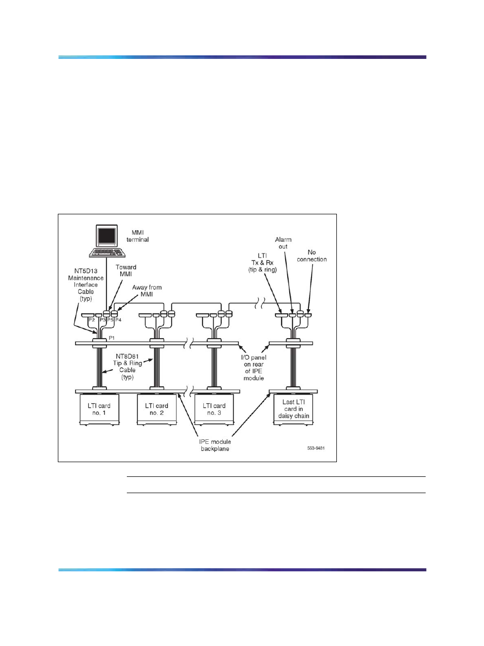
Figure 37
Lineside T1 card - connecting two or more cards to the MMI
—End—
P5 connector pins 2, 3, 5, 7 and 9 are used to connect the Lineside T1
card to the MMI terminal and daisy chain Lineside T1 cards together for
access to a shared MMI terminal. When logging into a Lineside T1 card,
"control 2" is asserted by that card, which informs all of the other cards not
Nortel Communication Server 1000
Circuit Card Reference
NN43001-311
01.04
Standard
Release 5.0
23 May 2008
Copyright © 2003-2008, Nortel Networks
.