Nt6d80 multi-purpose serial data link card, Table 28 nt6d68 core module backplane, Nt6d68 core module backplane – Nortel Networks Circuit Card 311 User Manual
Page 92
92
Option settings
NT6D68 Core module backplane
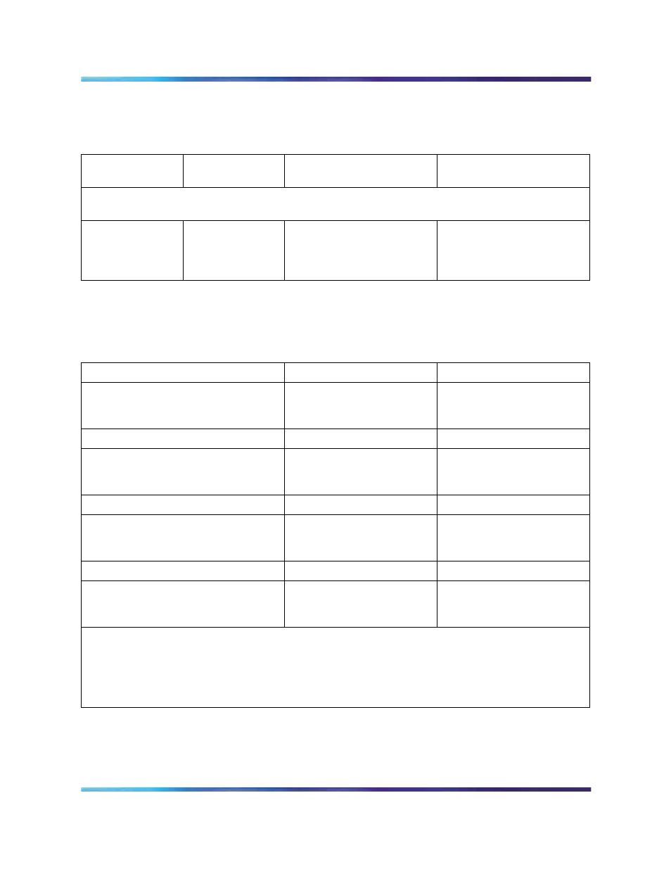
Table 28
NT6D68 Core module backplane
Jumper
Location
(between slots)
Core 1
Core 0
Note: Berg jumpers are located along the bottom of the primary side of the backplane. (This
is inside the card cage assembly.)
JB4
JB3
JB2
JB1
9 / 10
10 / 11
11 / 12
12 / 13
Jumper plug not installed
Plug installed
Plug installed
Plug installed
Plug installed
Plug installed
Plug installed
Plug installed
NT6D80 Multi-purpose Serial Data Link card
Table 29
NT6D80 Multi-purpose Serial Data Link card
Port 0—SW4
Port 0—SW8
RS-232-D DTE or DCE*
RS-422-A DTE (terminal)
RS-422-A DCE (modem)
all off
all off
all on
all off
all on
all off
Port 1—SW3
Port 1—SW7
RS-232-D DTE or DCE*
RS-422-A DTE
RS-422-A DCE
all off
all off
all on
all off
all on
all off
Port 2—SW2
Port 2—SW6
RS-232-D DTE or DCE*
RS-422-A DTE
RS-422-A DCE
all off
all off
all on
all off
all on
all off
Port 3—SW1
Port 3—SW5
RS-232-D DTE or DCE*
RS-422-A DTE
RS-422-A DCE
all off
all off
all on
all off
all on
all off
* RS-232-D DTE and DCE modes are software configured. RS-422-A DTE and DEC modes are
switch configured.
Note: The device number for the MSDL card is configured in LD17 at the prompt DNUM. You must
also set the device number, using switches S9 and S10, on the MSDL card. S9 designates ones
and S10 designates tens. To set the device number as 14, for example, set S10 to 1 and S9 to 4.
Nortel Communication Server 1000
Circuit Card Reference
NN43001-311
01.04
Standard
Release 5.0
23 May 2008
Copyright © 2003-2008, Nortel Networks
.