Figure 118 rj-11 or rj-45 jacks – Nortel Networks Circuit Card 311 User Manual
Page 485
Cabling
485
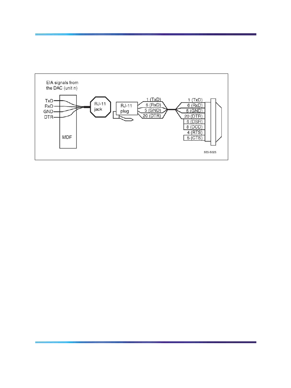
Note: It is necessary to turn over Receive Data and Send Data between
the DAC and the AILU. This is done on the TN at the MDF.
Figure 118
RJ-11 or RJ-45 jacks
Figure 119 "Patch panel layout" (page 486)
illustrates the patch panel.
RS-232-C cables are used to connect the data equipment to the patch
panel. This particular panel shows two 50-pin connectors into twelve
DB25. The signals from the MDF travel on 25-pair cables, terminating at
the patch panel.
Note: Use patch panels that follow the pinout of the DAC.
Figure 120 "Octopus cabling" (page 487)
describes an octopus cabling
scheme. This cable replaces the combined patch panel and RS-232-C
cabling scheme. The 25-pair cable is split into six RS-232-C male or female
connectors. This allows direct connections to the data equipment from the
I/O panel. The octopus cable allows for the maximum segregation of the
voice signals that might otherwise be present within the same 25-pair cable.
Nortel Communication Server 1000
Circuit Card Reference
NN43001-311
01.04
Standard
Release 5.0
23 May 2008
Copyright © 2003-2008, Nortel Networks
.