Figure 78 mmi local loopback test, Figure 79 mmi external loopback test, Figure 78 "mmi local – Nortel Networks Circuit Card 311 User Manual
Page 313
Man-Machine E1 maintenance interface software
313
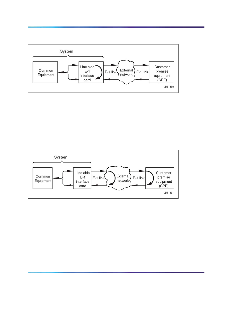
Figure 78
MMI Local loopback test
Test 2, external loopback, applies an external loopback to the E1 link. Test
data is generated and received by the LEI on all timeslots. If test 1 passes
but test 2 fails, it indicates that the E1 link is defective between the LEI and
the external loopback location. If test 1 was not run and test 2 fails, the E1
link or the LEI could be defective. To isolate the failure to the E1 link, tests 1
and 2 must be run in tandem.
Figure 79 "MMI External loopback test" (page
demonstrates how an external loopback is applied to the E1 link.
Figure 79
MMI External loopback test
Test 3, network loopback, loops the LEI’s received E1 data back toward the
CPE. No test data is generated or received by the LEI. If test 2 passes but
test 3 fails, it indicates that the CPE device is defective. If test 2 was not run
and test 3 fails, the E1 link or the CPE device could be defective. To isolate
the failure to the CPE device, tests 2 and 3 must be run in tandem.
80 "MMI Network loopback test" (page 314)
illustrates how the signaling is
looped back toward the CPE.
Nortel Communication Server 1000
Circuit Card Reference
NN43001-311
01.04
Standard
Release 5.0
23 May 2008
Copyright © 2003-2008, Nortel Networks
.