Front panel connector pin assignments, Table 72 com1 and com2 pin assignments – Nortel Networks Circuit Card 311 User Manual
Page 165
Front panel connector pin assignments
165
Memory
CP PIV memory uses DDR SDRAM technology. The CP PIV provides
a maximum of two GBytes using two verticall DIMM sockets to install
off-the-shelf DIMM modules. CP PIV only supports DDR SDRAM DIMM
memory with a supply voltage of +2.5V.
are supportedThe memory data path is 72-bit wide. The Intel 855GME Host
Bridge supports 64 Mbit, 128 MByte, 256 MByte and 512 Mbyte SDRAM
technologies with a maximum ROW page size of 16 Kbytes and CAS
latency of 2 or 2.5. The maximum height of the DIMM modules possible
on CP PIV is one inch or 25.4 mm.
The DDR interface runs at 100 MHz synchronously to the front side bus
frequency. The SPD (Serial Presents Detect) -SROM available on DIMM
modules provide all necessary information (speed, size, and type) to the
boot-up software. The SPD-SROM can be read via SMBUS connected to
the Intel Hance Rapids South Bridge.
Front panel connector pin assignments
COM1 and COM2 ports
The physical interface for the COM1 and COM2 ports to the front panel is
through a stacked dual Male DB9 Connector. The corresponding pin details
are shown in
Table 72 "COM1 and COM2 pin assignments" (page 165)
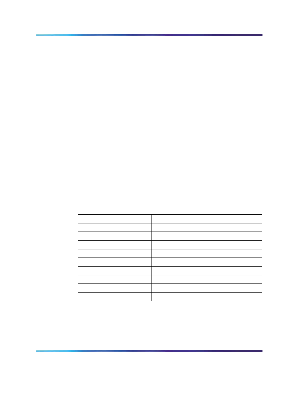
Table 72
COM1 and COM2 pin assignments
Pin number
Pin name
1
DCD
2
RXD
3
TXD
4
DTR
5
GND
6
DSR
7
RTS
8
CTS
9
RI
USB port
The physical interface for thetwo USB ports to the front panel is through a
standard USB connector. The corresponding Pin details are shown in
73 "USB connector pin outs" (page 166)
.Table 27. USB Connector Pin Outs
Nortel Communication Server 1000
Circuit Card Reference
NN43001-311
01.04
Standard
Release 5.0
23 May 2008
Copyright © 2003-2008, Nortel Networks
.