Figure 43 mmi local loopback test, Table 109 mmi tests – Nortel Networks Circuit Card 311 User Manual
Page 252
252
NT5D11 and NT5D14 Lineside T1 Interface cards
During a test, if an invalid word is received, a failure peg counter is
incremented. The peg counter saturates at 65,000 counts. At the end of the
test, the Test Results message indicates how many failures, if any, occurred
during the test.
Table 109 "MMI Tests" (page 252)
shows which test to run for the associated
equipment.
Table 109
MMI Tests
Test number
Equipment tested
Test description
1
Lineside T1 card
Local loopback
2
T1 link, Lineside T1 card
and T1 network
External loopback
3
CPE device and T1
network
Network loopback
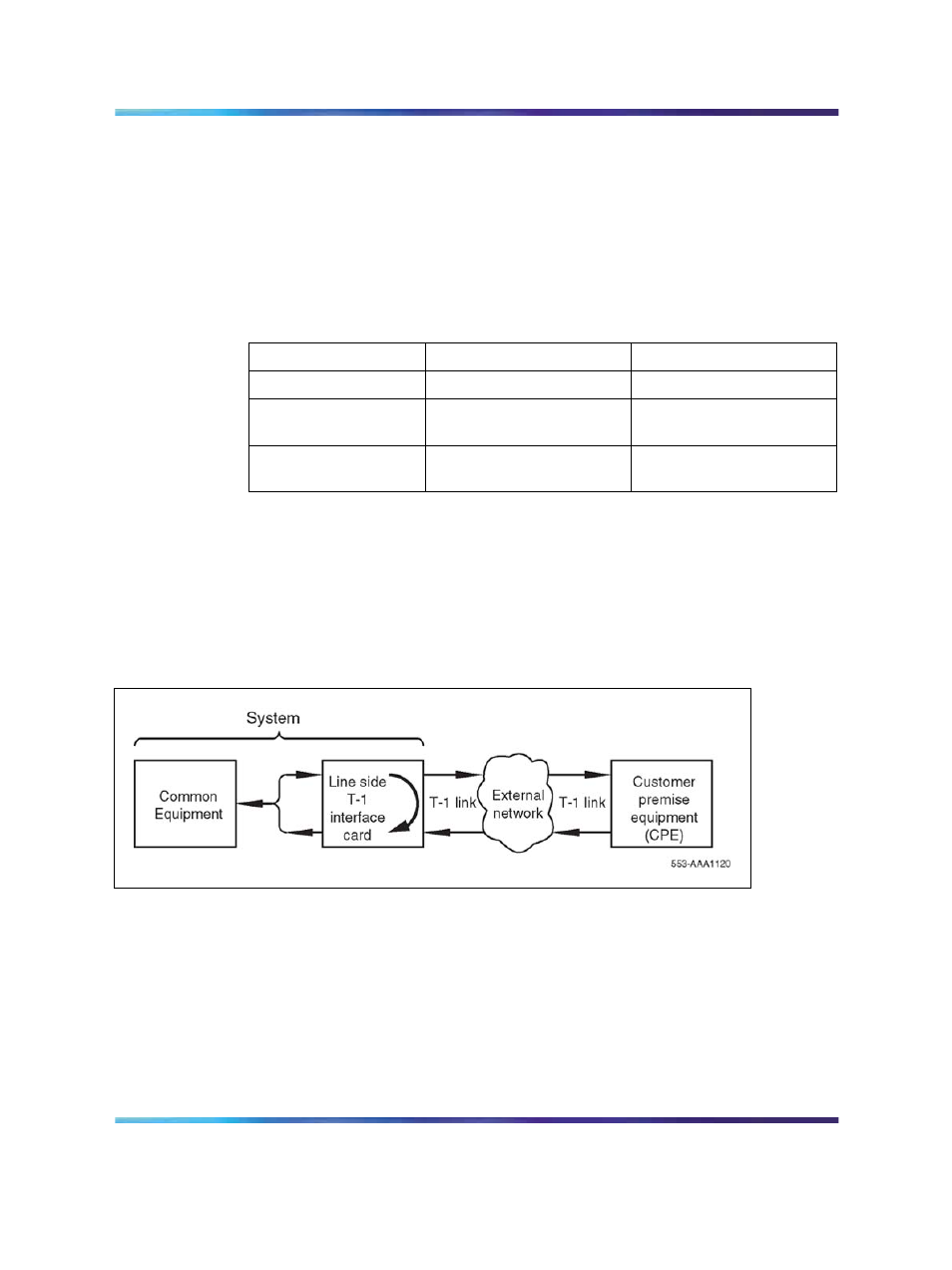
Test 1, local loopback, loops the T1 link signaling toward itself at the
backplane connector, and test data is generated and received on all
timeslots. If this test fails, it indicates that the Lineside T1 card is defective.
Figure 43 "MMI local loopback test" (page 252)
demonstrates how the
signaling is looped back toward itself.
Figure 43
MMI local loopback test
Test 2, external loopback, assumes an external loopback is applied to the
T1 link. Test data is generated and received by the Lineside T1 card on all
timeslots. If test 1 passes but test 2 fails, it indicates that the T1 link is
defective between the Lineside T1 card and the external loopback location.
If test 1 was not run and test 2 fails, the T1 link or the Lineside T1 card could
be defective. To isolate the failure to the T1 link, tests 1 and 2 must be run in
tandem.
Figure 44 "MMI external loopback test" (page 253)
demonstrates
how an external loopback is applied to the T1 link.
Nortel Communication Server 1000
Circuit Card Reference
NN43001-311
01.04
Standard
Release 5.0
23 May 2008
Copyright © 2003-2008, Nortel Networks
.