Table 76 itp connector pin outs – Nortel Networks Circuit Card 311 User Manual
Page 167
Front panel connector pin assignments
167
LED
Color
Functionality
Default
LED3
Green
CompactFlash activity
-Off
LED4
Green
CompactFlash activity
-Off
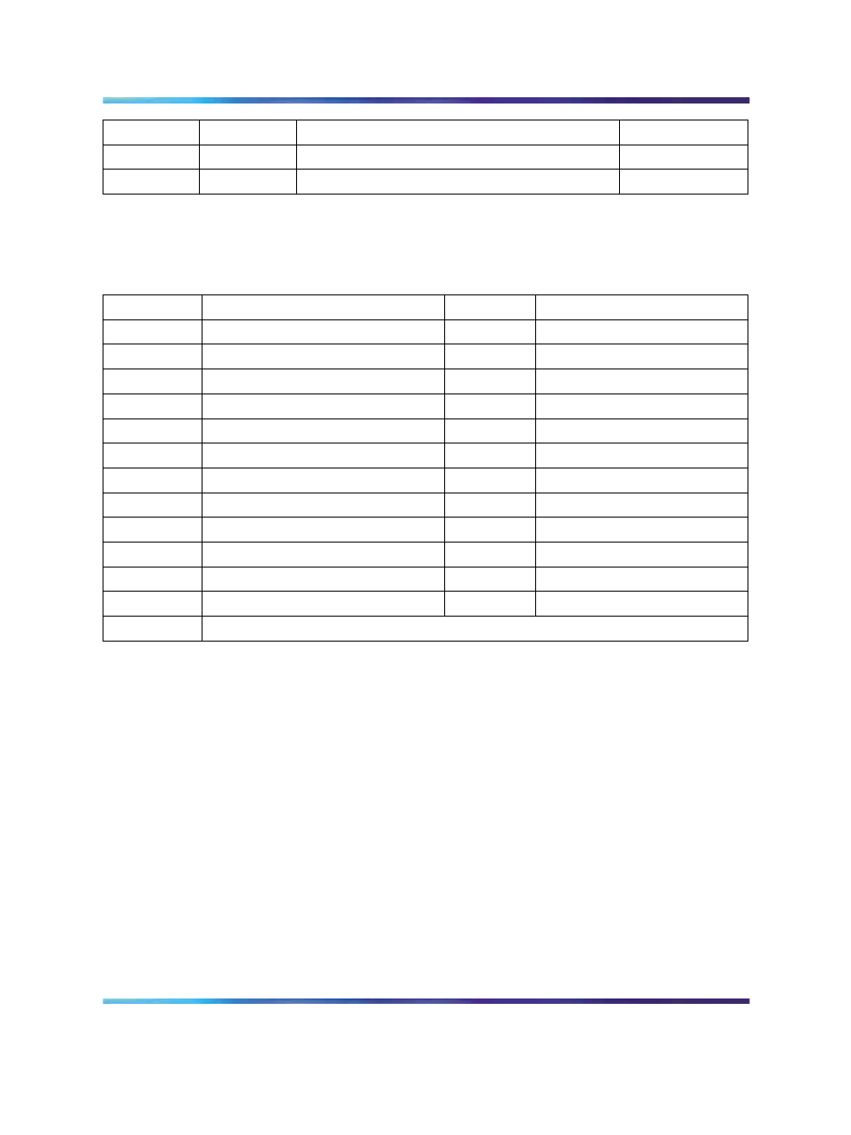
ITP connector (25 PIN, Debug Only)
Table 76
ITP connector pin outs
Pin
Signal Name
Pin
Signal Name
P1
GND
P2
GND
P3
BPM0N
P4
NC
P5
BPM1N
P6
RESETN
P7
BPM2N
P8
GND
P9
BPM3N
P10
TDI
P11
BPM4N
P12
TMS
P13
BPM5N
P14
TRSTN
P15
ITP_CPURSTN
P16
TCK
P17
TCK
P18
NC
P19
CLK
P20
GND
P21
CLKN
P22
PWR
P23
BPM5N
P24
TDO
P25
GND
Post 80 Debug LEDs (Optional)
CP PIV has post 80 debug LEDs to assist in debugging the board and
solving boot related problems. Using a GPCS from Super I/O X-bus, data
lines are latched using latch 74F374. These help identify Post 80 codes.
This feature is available only in debug boards.
Nortel Communication Server 1000
Circuit Card Reference
NN43001-311
01.04
Standard
Release 5.0
23 May 2008
Copyright © 2003-2008, Nortel Networks
.
- N300 (72 pages)
- Nortel Network VPN Router and Client Workstation 7.11 (67 pages)
- VT100 (97 pages)
- BSR222 (42 pages)
- COMMUNICATION SERVER 1000 NN43021-110 (70 pages)
- Media Dependent Adapters 302403-G (32 pages)
- Server 1005r (54 pages)
- 9115 (252 pages)
- CallPilot (2 pages)
- CTA 500dm (86 pages)
- CallPilot NN44200-700 (150 pages)
- NB5PLUS4/W (112 pages)
- Application Server 53r 5300 00 (124 pages)
- BayStack 893-862-B (12 pages)
- CWDM SFP (34 pages)
- NN43011-110 (48 pages)
- 9150 (562 pages)
- 5380 (7 pages)
- Server 600r (52 pages)
- Meridian 1 PC Console Interface Unit (4 pages)
- ROADSTER 56K (20 pages)
- Remote Gateway 50 (260 pages)
- Nortel Backbone Link Node Router 5030 (12 pages)
- Media Dependent Adapter (17 pages)
- 312865-A (18 pages)
- Meridian 11CM (4 pages)
- BSG12ew (66 pages)
- Passport ARN Routers (166 pages)
- Nortel Business Services Gateway BSG8ew (12 pages)
- WAG54G (100 pages)
- CALLPILOT 555-7101-215 (64 pages)
- 553-3901-200 (48 pages)
- NN44200-313 (66 pages)
- NN43021-110 (74 pages)
- WEB OS 212777 (482 pages)
- CTA 150i (2 pages)
- 2332 (102 pages)
- 8000 (486 pages)
- NN43001-318 (108 pages)
- HotWire 8600 (62 pages)
- 2330 (40 pages)
- Mediant TP-1610 SIP (280 pages)
- NN46110-602 (230 pages)
- Circuit Card (908 pages)