2 configuration of 8/16-bit capture timer/counter, Configuration of 8/16-bit capture timer/counter, Block diagram of 8/16-bit capture timer/counter – FUJITSU F2MC-8L F202RA User Manual
Page 182
166
CHAPTER 8 8/16-BIT CAPTURE TIMER/COUNTER
8.2
Configuration of 8/16-bit Capture Timer/Counter
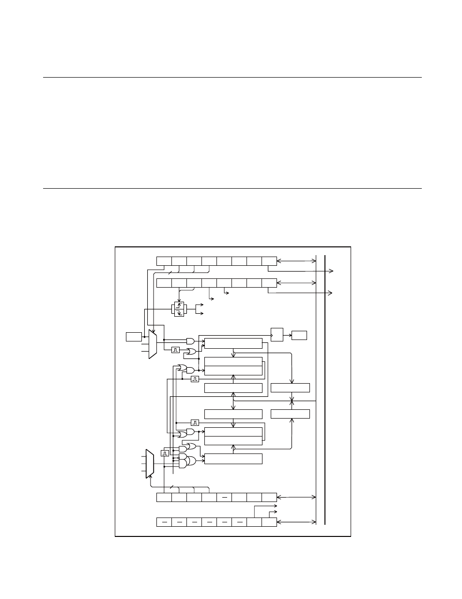
The 8/16-bit capture timer/counter consists of the following seven blocks:
• Count clock selectors 0/1
• Counter circuits 0/1
• Square wave output control circuit
• Timer 0/1 data registers (TDR0, TDR1)
• Timer 0/1 control registers (TCR0, TCR1)
• Capture data registers (TCPL, TCPH)
• Timer output control register (TCR2)
■
Block Diagram of 8/16-bit Capture Timer/Counter
Figure 8.2-1 Block Diagram of 8/16-bit Capture Timer/Counter
Counter clear
mask (capture clr)
Counter clear mask (identity clr)
Counter clear
Capture latch
Inter
nal data b
u
s
8-bit mode
Port output enable
Timer0, Timer1
output selection
CK0
TDR0
TDR1
TIF0
TFCR0
T0IEN
CINV
TCS02
TCS01
TCS00
TSTR0
TIF1
TFCR1
T1IEN
TCS12
TCS11
TCS10
TSTR
1
CK6
to
to
CO
CK
EQ
CLR
Q
TFF
EQ
CLR
CK
CK6
CK0
3
3
CPIF
CFCLR
CPIEN
CCMSK
TCMSK
EDGS1
EDGS0
RESV
TCR0
TCCR
TCPL
TCR1
TCPH
P34/TO/ INT10
P33/EC
TSEL
PEN
TCR2
M
P
X
M
P
X
IRQ3
IRQ4
8-bit counter
"
L
"
Comparator
LOAD comparator latch
Data register
"
L
"
Pin
Pin
Capture register
"
L
"
Capture register
"
H
"
Data register
"
H
"
8-bit counter
"
H
"
Comparator
LOAD comparator latch