FUJITSU F2MC-8L F202RA User Manual
Page 169
153
CHAPTER 7 8-BIT PWM TIMER
●
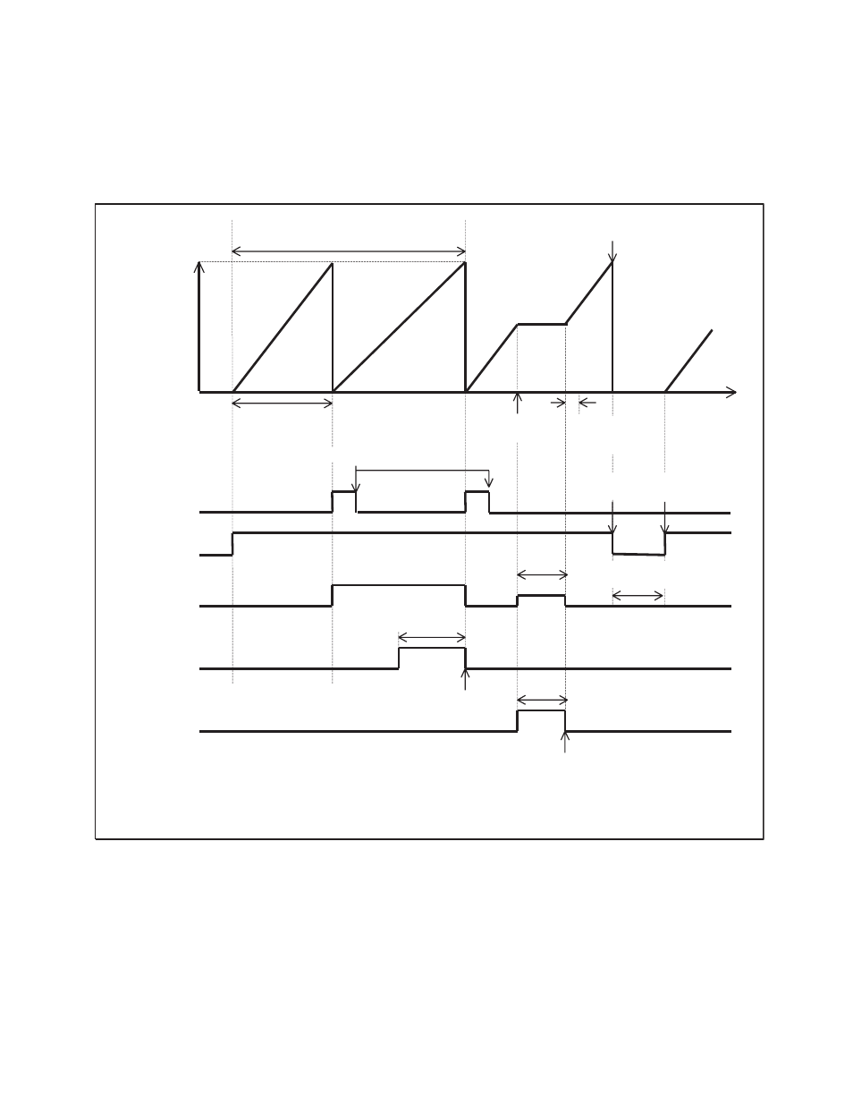
While interval timer functions are enabled:
Figure 7.8-1 Operation of the Counter in the Standby Mode and during Suspension (while Interval
Functions are Enabled)
00
H
Co
u
nter v
a
l
u
e
FF
H
COMR v
a
l
u
e (FF
H
)
Cle
a
r
b
y
s
topping oper
a
tion
Timer cycle
S
top
re
qu
e
s
t
Time to w
a
it
for o
s
cill
a
tion
s
t
ab
iliz
a
tion
Time
Cle
a
r
b
y the progr
a
m
S
topping
oper
a
tion
Re
s
t
a
rting
oper
a
tion
TIR
b
it
TPE
b
it
PWM pin
(OE = 1)
*
"
L
"
level while oper
a
tion
i
s
b
eing
s
topped
S
LP
b
it
(
S
TBC
regi
s
ter)
S
leep
Rele
as
e of
s
leep
b
y IRQ9
S
top
S
TP
b
it
(
S
TBC
regi
s
ter)
Rele
as
e of
s
top
b
y
a
n extern
a
l interr
u
pt
When the
b
it to
s
pecify the pin
s
t
a
te (
S
TBC:
S
PL) of the
s
t
a
nd
b
y control regi
s
ter i
s
"1",
a
nd
the PWM pin i
s
not p
u
lled
u
p, the PWM pin in the
s
top mode i
s
Hi-Z. When the
S
PL
b
it i
s
"0", the
v
a
l
u
e immedi
a
tely
b
efore the move to the
s
top mode i
s
held.
*: