3 pin of 8-bit pwm timer, Pin of 8-bit pwm timer, Pin related to the 8-bit pwm timer – FUJITSU F2MC-8L F202RA User Manual
Page 157
141
CHAPTER 7 8-BIT PWM TIMER
7.3
Pin of 8-bit PWM Timer
This section describes the pin and provides a block diagram of the pin related to the 8-
bit PWM timer.
■
Pin Related to the 8-bit PWM Timer
The pin related to the 8-bit PWM timer is the P50/PWM pin.
●
P50/PWM pin
This pin can be used as a general-purpose I/O port (P50) and for output of the interval timer or PWM timer
(PWM).
PWM:
While the pin functions as the interval timer, the square wave is output to the pin.
While the pin functions as the PWM timer, the PWM wave is output to the pin.
When the bit to control the output pin is set to the dedicated pin (CNTR: OE = 1), the P50/PWM pin
automatically functions as an output pin, regardless of the value of the port 5 data direction register
(DDR5: bit0), and as the PWM pin.
■
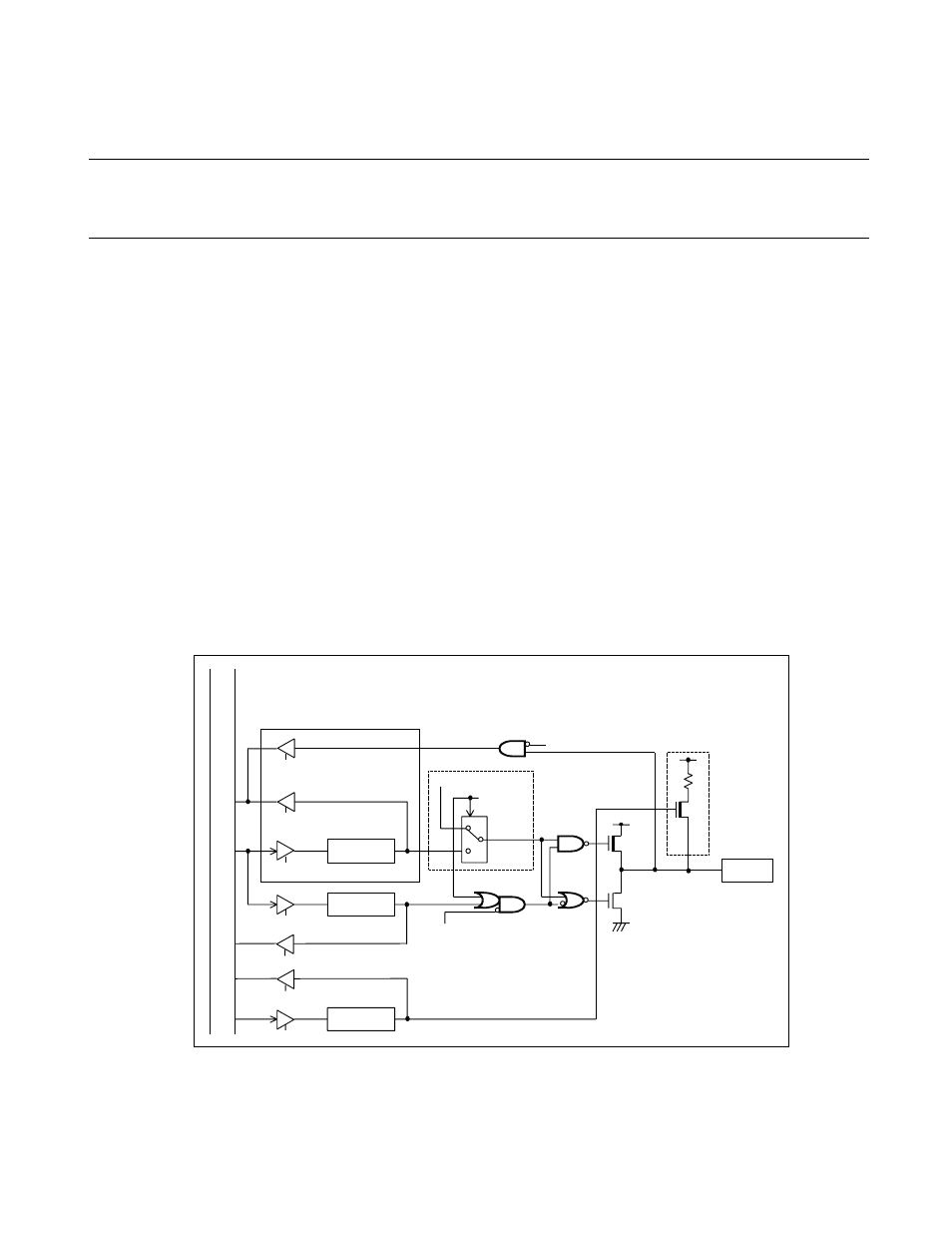
Block Diagram of the Pin Related to the 8-bit PWM Timer
Figure 7.3-1 Block Diagram of the Pin Related to the 8-bit PWM Timer
DDR
Pch
Nch
PDR
PUL
P50/PWM
(
S
PL=1)
S
top mode (
S
PL=1)
P
u
ll-
u
p re
s
i
s
tor
PDR re
a
d
Re
s
o
u
rce o
u
tp
u
t
Re
s
o
u
rce
o
u
tp
u
t i
s
en
ab
led
(At re
a
d-modify-write)
PDR re
a
d
Inter
n
a
l d
a
t
a
bu
s
O
u
tp
u
t l
a
tch
PDR write
Pin
DDR write
PUL re
a
d
PUL write
S
top mode
DDR re
a
d