2 configuration of 8-bit pwm timer, Configuration of 8-bit pwm timer – FUJITSU F2MC-8L F202RA User Manual
Page 155
139
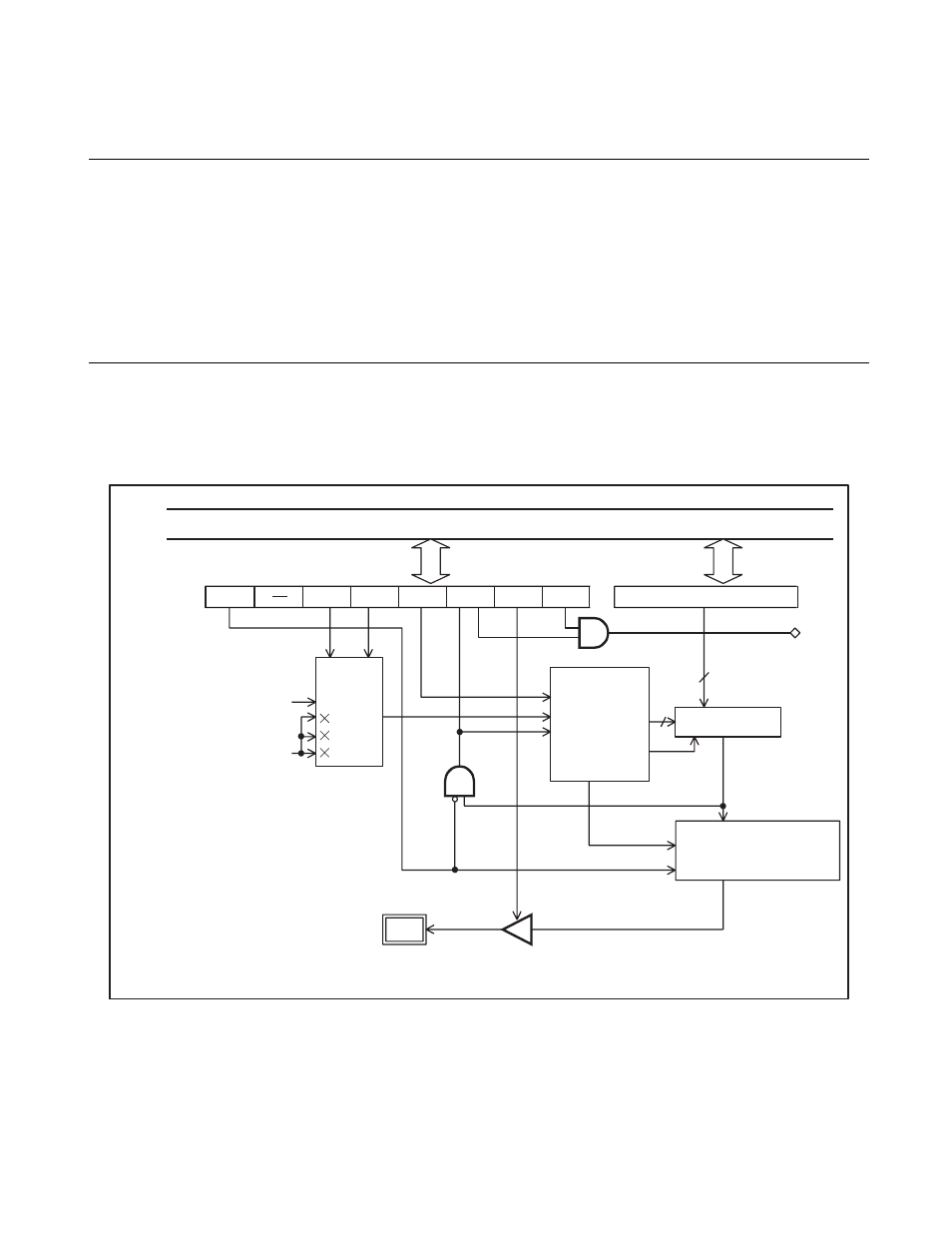
CHAPTER 7 8-BIT PWM TIMER
7.2
Configuration of 8-bit PWM Timer
An 8-bit PWM timer consists of the following six blocks.
• Count clock selector
• 8-bit counter
• Comparator
• PWM generation and output control circuit
• PWM compare register (COMR)
• PWM control register (CNTR)
■
Block Diagram of an 8-bit PWM Timer
Figure 7.2-1 Block Diagram of an 8-bit PWM Timer
t
INST
: Instruction cycle
P/TX
P1
P0
TPE
TIR
OE
TIE
CLK
ECLK
1
16
64
1t
INST
CNTR
COMR
IRQ9
TO
P50/PWM
8
8
Internal data bus
PWM compare register
(Output of an 8/16-bit
capture timer/counter)
Count
clock
selector
8-bit counter
Start
Clear
Latch
Overflow
Comparator
Timer/
PWM
PWM generation
circuit and output
control circuit
Output pin control
Pin
Output
This manual is related to the following products: