Switches and jumpers on the terminal board, 9 control circuit wiring – Yaskawa Z1000U User Manual
Page 87
u
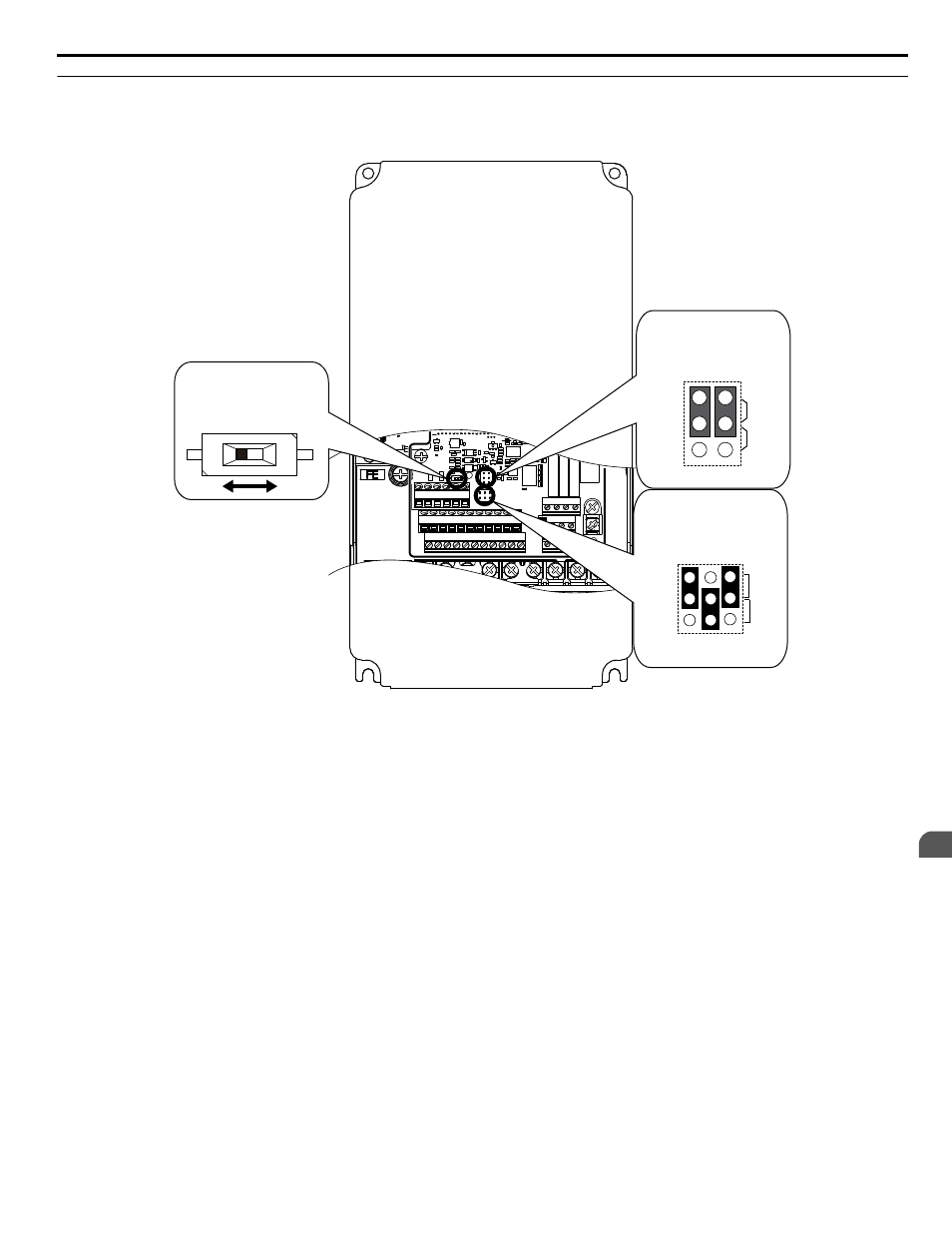
Switches and Jumpers on the Terminal Board
The terminal board is equipped with several switches used to adapt the drive I/Os to the external control signals.
shows the location of these switches.
Refer to Control I/O Connections on page 88
for setting instructions.
E(G) IG R+ R- S+ S-
S1 S2 S3 S4 S5 S6 S7 S8 SN SC SP
V+ AC A1 A2 A3 FM AM AC
24V
RP AC
M1 M2 M3 M4
MD ME MF
MA MB MC
Selection
Jumper S5
Terminal AM/FM Signal
DIP Switch S2
RS-422/RS-485
Termination Resistor
Off
On
Jumper S1
A1/A2/A3 Volt/Curr.
Selection
V
I
A1 A2 A3
V
AM
FM
I
Figure 3.39 Locations of Jumpers and Switches on the Terminal Board
3.9 Control Circuit Wiring
YASKAWA ELECTRIC TOEP C710636 10B Z1000U HVAC MATRIX Drive User Manual
87
3
Electrical Installation
This manual is related to the following products: