7 basic drive setup adjustments – Yaskawa Z1000U User Manual
Page 119
The wait time t is determined by the output frequency when the Run command is removed and by the active deceleration time.
Min output
frequency
100%
(Max output
frequency)
Output frequency
when Stop command
was entered
Run wait time t
Active deceleration time
Momentary Power Loss
Minimum Baseblock
Time (L2-03)
Figure 4.18 Run Wait Time Depending on Output Frequency
n
C1-01 to C1-04: Accel, Decel Times 1 and 2
Four different sets of acceleration and deceleration times can be set in the drive by digital inputs, motor selection, or switched
automatically.
Acceleration time parameters always set the time to accelerate from 0 Hz to the maximum output frequency (E1-04).
Deceleration time parameters always set the time to decelerate from maximum output frequency to 0 Hz. C1-01 and C1-02
are the default active accel/decel settings.
No.
Parameter Name
Setting Range
Default
C1-01
Acceleration Time 1
0.1 to 6000.0 s
30.0 s
C1-02
Deceleration Time 1
C1-03
Acceleration Time 2
C1-04
Deceleration Time 2
Switching Acceleration Times by Digital Input
Accel/decel times 1 are active by default if no input is set.
Table 4.17 Accel/Decel Time Selection by Digital Input
Accel/Decel Time Sel. 1
H1-oo = 7
Active Times
Acceleration
Deceleration
0
C1-01
C1-02
1
C1-03
C1-04
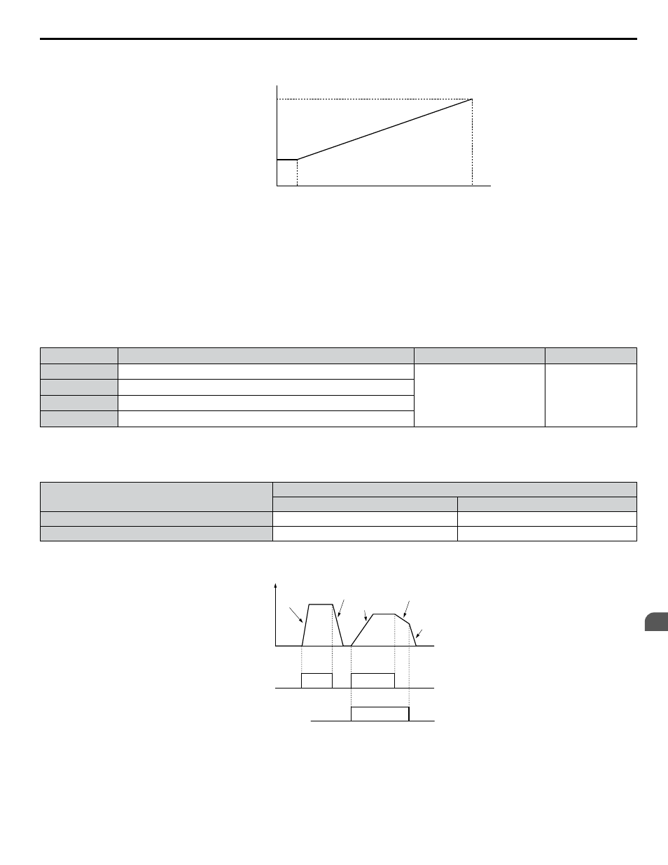
shows an operation example for changing accel/decel. times. The example below requires that the stopping method
be set for “Ramp to stop” (b1-03 = 0).
Output
frequency
Accel Time 1
(C1-01)
Decel Time 1
(C1-02)
Accel Time 2
(C1-03)
Decel Time 2
(C1-04)
Decel Time 1
(C1-02)
FWD (REV)
Run command
ON
OFF
ON
ON
Accel/Decel Time Selection 1
(Terminals S1 to S7, H1-oo = “7”)
Figure 4.19 Timing Diagram of Accel/Decel Time Change
4.7 Basic Drive Setup Adjustments
YASKAWA ELECTRIC TOEP C710636 10B Z1000U HVAC MATRIX Drive User Manual
119
4
Start-Up Programming & Operation