Select the different speed references as shown in, Table 4.25, Figure 4.33 – Yaskawa Z1000U User Manual
Page 158: D2-03: master speed reference lower limit
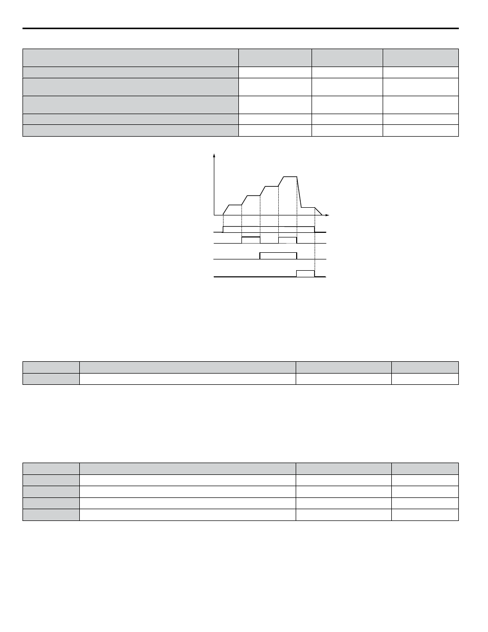
Table 4.25 Multi-Step Speed Reference and Terminal Switch Combinations
Reference
Multi-Step Speed
H1-oo = 3
Multi-Step Speed 2
H1-oo = 4
Jog Reference
H1-oo = 6
Frequency Reference 1 (set in b1-01)
OFF
OFF
OFF
Frequency Reference 2
(d1-02 or input terminal A1, A2)
ON
OFF
OFF
Frequency Reference 3
(d1-03 or input terminal A1, A2)
OFF
ON
OFF
Frequency Reference 4 (d1-04)
ON
ON
OFF
Jog Frequency Reference (d1-17)
<1>
−
−
ON
<1> The Jog frequency overrides all other frequency references.
d1-04
d1-17
ON
ON
ON
ON
ON
Multi-step Speed Ref. 2
Jog Reference
Time
Multi-step Speed Ref. 1
Frequency
reference
d1-01
(A1)
d1-02
(A2)
d1-03
FWD (REV) Run/Stop
Figure 4.33 Preset Reference Timing Diagram
n
d2-03: Master Speed Reference Lower Limit
Sets a lower limit as a percentage of the maximum output frequency that will only affect a frequency reference entered from
the analog input terminals (A1, A2, or A3) as the master speed reference. This is unlike parameter d2-02, which affects all
frequency references regardless of their source.
Note:
When lower limits are set to both parameters d2-02 and d2-03, the drive uses the greater of those two values as the lower limit.
No.
Parameter Name
Setting Range
Default
d2-03
Master Speed Reference Lower Limit
0.0 to 110.0%
0.0%
n
d3-01 to d3-04: Jump Frequencies 1, 2, 3 and Jump Frequency Width
The Jump frequencies are frequency ranges at which the drive will not operate. The drive can be programmed with three
separate Jump frequencies to avoid operating at speeds that cause resonance in driven machinery. If the speed reference falls
within a Jump frequency dead band, the drive will clamp the frequency reference just below the dead band and only accelerate
past it when the frequency reference rises above the upper end of the dead band.
Setting parameters d3-01 through d3-03 to 0.0 Hz disables the Jump frequency function.
No.
Parameter Name
Setting Range
Default
d3-01
Jump Frequency 1
0.0 to 400.0 Hz
0.0 Hz
d3-02
Jump Frequency 2
0.0 to 400.0 Hz
0.0 Hz
d3-03
Jump Frequency 3
0.0 to 400.0 Hz
0.0 Hz
d3-04
Jump Frequency Width
0.0 to 20.0 Hz
1.0 Hz
shows the relationship between the Jump frequency and the output frequency.
4.12 Advanced Drive Setup Adjustments
158
YASKAWA ELECTRIC TOEP C710636 10B Z1000U HVAC MATRIX Drive User Manual