H3: multi-function analog inputs, For descriptions of setting values – Yaskawa Z1000U User Manual
Page 284
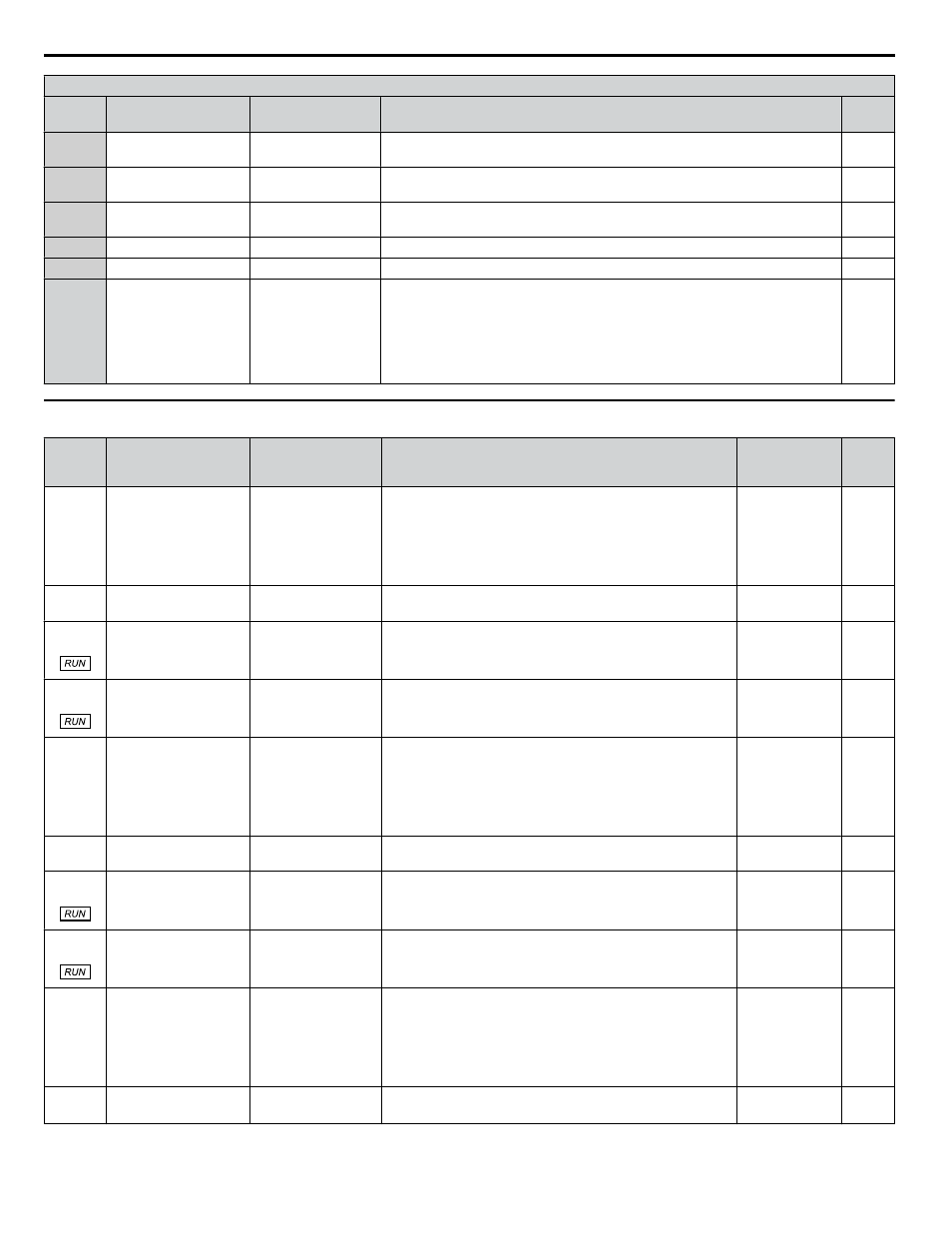
H2 Multi-Function Digital Output Settings
H2-oo
Setting
Function
LCD Display
Description
Page
B2
BAS Interlock Relay
Contact
BAS Interlock
A Run command is active or voltage is output. Actuation signal for damper.
–
B3
Secondary PI Feedback
Low
PI2 Feedback Low
Closed: PI2 feedback level is too low.
–
B4
Secondary PI Feedback
High
PI2 FeedbackHigh
Closed: The PI2 feedback level is too high.
–
B5
Relay Operator Control PI2 Disable N.C.
Closed: F1 (F2) key toggle relay output.
–
B6
Drive overheat alarm 2 OH Alarm 2
Closed: An external device triggered an overheat warning in the drive.
–
100 to
1B6
Function 0 to B6 with
inverse output
Note: A prefix of "!" is
added to represent
inverse functions on the
LCD keypad display.
Example: “!Zero speed”
–
Inverts the output switching of the multi-function output functions.
Set the last two digits of 1oo to reverse the output signal of that specific function.
–
u
H3: Multi-Function Analog Inputs
No.
(Addr.
Hex)
Name
LCD Display
Description
Values
Page
H3-01
(0410)
Terminal A1 Signal
Level Selection
Term A1 Level
0: 0-10V,
(LowLim=0)
1: 0-10V, (BipolRef)
2: 4-20 mA
3: 0-20 mA
0: 0 to 10 V with zero limit
1: 0 to 10 V without zero limit
2: 4-20 mA
3: 0-20 mA
Note:
Use jumper switch S1 to set input terminal A1
for current or voltage.
Default: 0
Range: 0 to 3
H3-02
(0434)
Terminal A1 Function
Selection
Term A1 FuncSel
Sets the function of terminal A1.
Default: 0
Range: 0 to 26
H3-03
(0411)
Terminal A1 Gain
Setting
Terminal A1 Gain
Sets the level of the input value selected in H3-02 when 10 V
is input at terminal A1.
Default: 100.0%
Min.: -999.9
Max.: 999.9
H3-04
(0412)
Terminal A1 Bias
Setting
Terminal A1 Bias
Sets the level of the input value selected in H3-02 when 0 V is
input at terminal A1.
Default: 0.0%
Min.: -999.9
Max.: 999.9
H3-05
(0413)
Terminal A3 Signal
Level Selection
Term A3 Signal
0: 0-10V (LowLim=0)
1: 0-10V, (BipolRef)
2: 4-20mA
3: 0-20mA
0: 0 to 10 V
1: -10 to 10 V
2: 4 to 20 mA
3: 0 to 20 mA
Note:
Use jumper switch S1 to set input terminal A3
for current or voltage input signal.
Default: 0
Range: 0 to 3
H3-06
(0414)
Terminal A3 Function
Selection
Terminal A3 Sel
Sets the function of terminal A3.
Default: 2
Range: 0 to 26
H3-07
(0415)
Terminal A3 Gain
Setting
Terminal A3 Gain
Sets the level of the input value selected in H3-06 when 10 V
is input at terminal A3.
Default: 100.0%
Min.: -999.9
Max.: 999.9
–
H3-08
(0416)
Terminal A3 Bias
Setting
Terminal A3 Bias
Sets the level of the input value selected in H3-06 when 0 V is
input at terminal A3.
Default: 0.0%
Min.: -999.9
Max.: 999.9
–
H3-09
(0417)
Terminal A2 Signal
Level Selection
Term A2 Level
0: 0-10V,
(LowLim=0)
1: 0-10V, (BipolRef)
2: 4-20 mA
3: 0-20 mA
0: 0 to 10 V with zero limit
1: 0 to 10 V without zero limit
2: 4 to 20 mA
3: 0 to 20 mA
Note:
Use jumper switch S1 to set input terminal A2
for current or voltage input signal.
Default: 2
Range: 0 to 3
H3-10
(0418)
Terminal A2 Function
Selection
Term A2 FuncSel
Sets the function of terminal A2.
Default:
<1>
Range: 0 to 26
B.8 H Parameters: Multi-Function Terminals
284
YASKAWA ELECTRIC TOEP C710636 10B Z1000U HVAC MATRIX Drive User Manual