Configuration, reduce the ground currents, C6-02: carrier frequency selection, D2-01: frequency reference upper limit – Yaskawa Z1000U User Manual
Page 120
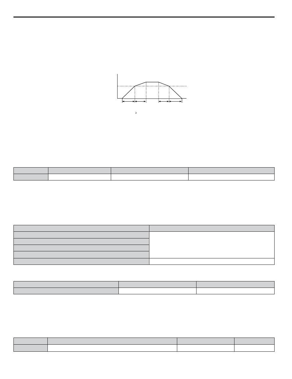
Switching Accel/Decel Times by a Frequency Level
The drive can switch between different acceleration and deceleration times automatically. The drive will switch from accel/
decel time 2 in C1-03 and C1-04 to the default accel/decel time in C1-01 and C1-02 when the output frequency exceeds the
frequency level set in parameter C1-11. When the frequency falls below this level, the accel/decel times are switched back.
shows an operation example.
Note:
Acceleration and deceleration times selected by digital inputs have priority over the automatic switching by the frequency level set to C1-11.
For example, if accel/decel time 2 is selected, the drive will use only accel/decel time 2; it will not switch from accel/decel time 2 to the
selected time.
Output Frequency
C1-11
Accel/Decel Time
Switch Frequency
C1-03
setting
When the output frequency C1-11, drive uses Accel/Decel Time 1 (C1-01, -02)
When the output frequency < C1-11, drive uses Accel/Decel Time 2 (C1-03, -04)
C1-01
setting
C1-02
setting
C1-04
setting
Figure 4.20 Accel/Decel Time Switching Frequency
n
C6-02: Carrier Frequency Selection
Sets the switching frequency of the drive output transistors. Changes to the switching frequency lower audible noise and reduce
leakage current.
Note:
Increasing the carrier frequency above the default value automatically lowers the drive current rating.
Refer to Rated Current Depending
on Carrier Frequency on page 249
.
No.
Parameter Name
Setting Range
Default
C6-02
Carrier Frequency Selection
1 to 4, F
Determined by A1-02 and o2-04.
Setting 1: 4.0 kHz
Setting 2: 6.0 kHz
Setting 3: 8.0 kHz
Setting 4: 10.0 kHz
Setting F: User defined (C6-03 to C6-05)
Guidelines for Carrier Frequency Parameter Setup
Symptom
Remedy
Speed and torque are unstable at low speeds
Lower the carrier frequency.
Noise from the drive affects peripheral devices
Excessive leakage current from the drive
Wiring between the drive and motor is too long
<1>
Audible motor noise is too loud
Increase the carrier frequency.
<1> The carrier frequency may need to be lowered if the motor cable is too long. Refer to
Table 4.18
.
Table 4.18 Wiring Distance and Carrier Frequency
Wiring Distance
Up to 50 m
Greater than 50 m
Recommended setting value for C6-02
1 to 4 (up to 10 kHz)
1 (up to 4 kHz)
Note:
The maximum cable length is 100 m when using OLV/PM (A1-02 = 5).
n
d2-01: Frequency Reference Upper Limit
Sets the maximum frequency reference as a percentage of the maximum output frequency. This limit applies to all frequency
references.
Even if the frequency reference is set to a higher value, the drive internal frequency reference will not exceed this value.
No.
Parameter Name
Setting Range
Default
d2-01
Frequency Reference Upper Limit
0.0 to 110.0%
100.0%
4.7 Basic Drive Setup Adjustments
120
YASKAWA ELECTRIC TOEP C710636 10B Z1000U HVAC MATRIX Drive User Manual