Refer to, Refer to wiring the main circuit terminal on, Cover – Yaskawa Z1000U User Manual
Page 81: Refer to wiring, Wiring the main circuit terminal, Main circuit connection diagram
A
B
B
A
n1 p1
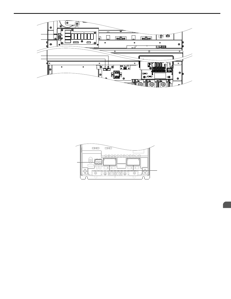
A – SW (ON)
B – Screw (OFF)
Figure 3.32 EMC Filter Switch Location
(Models 4E0302 to 4E0414 and 4W0302 to 4W0414)
n
Wiring the Main Circuit Terminal
WARNING! Electrical Shock Hazard. Shut off the power supply to the drive before wiring the main circuit terminals. Failure to comply may
result in death or serious injury.
Wire the main circuit terminals after the terminal board has been properly grounded.
Models 2o0028 to 2o0081 and 4o0011 to 4o0077 have a cover placed over terminals p1 and n1 prior to shipment to help
prevent miswiring. Use wire cutters to cut away covers as needed for terminals.
CHARGE
n1
p1
R/L1 S/L2 T/L3
U/T1 V/T2 W/T3
A
B
A – Protective cover for terminals p1
and n1
B – Main circuit protective cover
Figure 3.33 Protective Cover to Prevent Miswiring
n
Main Circuit Connection Diagram
Refer to Main Circuit Connection Diagram on page 59
when wiring terminals on the main power circuit of the drive.
3.8 Main Circuit Wiring
YASKAWA ELECTRIC TOEP C710636 10B Z1000U HVAC MATRIX Drive User Manual
81
3
Electrical Installation