Yaskawa Z1000U User Manual
Page 314
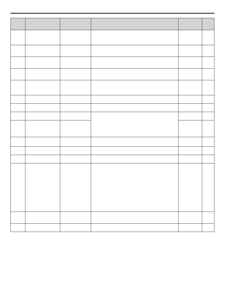
No.
(Addr.
Hex)
Name
LCD Display
Description
Analog
Output Level
Unit
U4-03
(0067)
Cooling Fan Operation
Time
Fan Elapsed TIme
Displays the cumulative operation time of the cooling fan. The
default value for the fan operation time is reset in parameter
o4-03. This value will reset to 0 and start counting again after
reaching 99999.
No signal output
available
1 h
U4-04
(007E)
Cooling Fan
Maintenance
Fan Life Mon
Displays main cooling fan usage time as a percentage of its
expected performance life. Parameter o4-03 can be used to reset
this monitor.
No signal output
available
1%
U4-05
(007C) Capacitor Maintenance Cap Life Mon
Displays main circuit capacitor usage time as a percentage of their
expected performance life. Parameter o4-05 can be used to reset
this monitor.
No signal output
available
1%
U4-06
(07D6)
Soft Charge Bypass
Relay Maintenance
ChgCirc Life Mon
Displays the soft charge bypass relay maintenance time as a
percentage of its estimated performance life. Parameter o4-07 can
be used to reset this monitor.
No signal output
available
1%
U4-07
(07D7) IGBT Maintenance
IGBT Life Mon
Displays IGBT usage time as a percentage of the expected
performance life. Parameter o4-09 can be used to reset this
monitor.
Replace the IGBT when this monitor reaches 90%.
No signal output
available
1%
U4-08
(0068) Heatsink Temperature
Heatsink Temp
Displays the heatsink temperature.
10 V: 100 °C
1 °C
U4-09
(005E) LED Check
LED Oper Check
Lights all segments of the LED to verify that the display is
working properly.
No signal output
available
–
U4-10
(005C) kWh, Lower 4 Digits
kWh Lower 4 dig
Monitors the drive output power. The value is shown as a 9-digit
number displayed across two monitor parameters, U4-10 and
U4-11.
Example:
12345678.9 kWh is displayed as:
U4-10: 678.9 kWh
U4-11: 12345 MWh
No signal output
available
1 kWh
U4-11
(005D) kWh, Upper 5 Digits
kWh Upper 5 dig
No signal output
available
1 MWh
U4-13
(07CF) Peak Hold Current
Current PeakHold
Displays the highest current value that occurred during run.
No signal output
available
0.01 A
<1>
U4-14
(07D0)
Peak Hold Output
Frequency
Freq@ I PeakHold
Displays the output frequency when the current value shown in
U4-13 occurred.
No signal output
available
0.01 Hz
U4-16
(07D8)
Motor Overload
Estimate (oL1)
Motor OL1 Level
Shows the value of the motor overload detection accumulator.
100% is equal to the oL1 detection level.
10 V: 100%
0.1%
U4-18
(07DA)
Frequency Reference
Source Selection
Reference Source
Displays the source for the frequency reference as XY-nn.
X: indicates which reference is used:
0 = OFF
1 = AUTO
2 = HAND
Y-nn: indicates the reference source
0-01 = HOA keypad
1-00 = Analog (not assigned)
1-01 = Analog (terminal A1)
1-02 = Analog (terminal A2)
2-02 to 17 = Multi-step speed (d1-02 to 17)
3-01 = MEMOBUS/Modbus communications
4-01 = Communication option card
9-01 = Up/Down
No signal output
available
–
U4-19
(07DB)
Frequency Reference
from MEMOBUS/
Modbus Comm.
MEMOBUS Freq Ref
Displays the frequency reference provided by MEMOBUS/
Modbus (decimal).
No signal output
available
0.01%
U4-20
(07DC)
Option Frequency
Reference
Option Freq Ref
Displays the frequency reference input by an option card
(decimal).
No signal output
available
–
B.14 U: Monitors
314
YASKAWA ELECTRIC TOEP C710636 10B Z1000U HVAC MATRIX Drive User Manual