Fine-tuning open loop vector control for pm motors – Yaskawa Z1000U User Manual
Page 187
u
Fine-Tuning Open Loop Vector Control for PM Motors
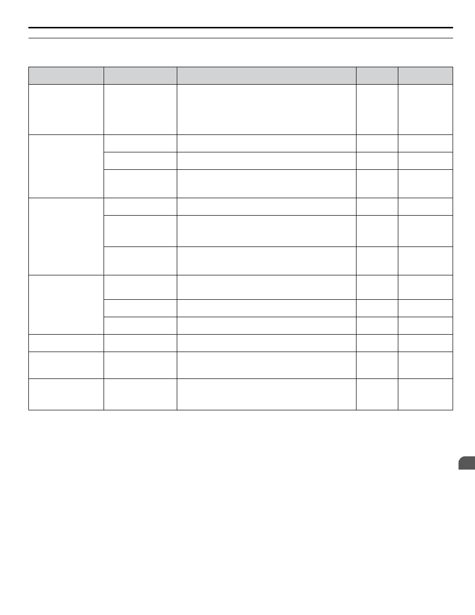
Table 5.2 Parameters for Fine-Tuning Performance in OLV/PM
Problem
Parameter No.
Corrective Action
Default
Suggested
Setting
Undesirable motor
performance
Motor parameters
(E1-oo, E5-oo)
• Check the settings for base and maximum frequency in the
E1-oo parameters.
• Check E5-oo parameters and set motor data correctly. Do
not enter line-to-line data where single-phase data is required,
and vice versa.
• Perform Auto-Tuning.
-
-
Poor motor torque and
speed response
Load Inertia Ratio
(n8-55)
Adjust parameter n8-55 to meet the load inertia ratio of the
machine.
0
Close to the actual
load inertia ratio
Speed Feedback
Detection Gain (n8-45)
Increase the speed feedback detection gain (n8-45).
0.80
Increase in
increments of 0.05
Torque Compensation
(C4-01)
Enable torque compensation.
Note:
Setting this value too high can cause
overcompensation and motor oscillation.
0.00
1.00
Oscillation at start or the
motor stalls
Pull-In Current during
Accel/Decel (n8-51)
Increase the pull-in current in n8-51
50%
Increase in steps
of 5%
DC Injection Braking
Current (b2-02), DC
Injection Time at Start
(b2-03)
Use DC Injection Braking at start to align the rotor. This may
cause a short reverse rotation at start.
b2-02 = 50%
b2-03 = 0.00 s
b2-03 = 0.5 s
Increase b2-02 if
needed
Load Inertia Ratio
(n8-55)
Increase the load inertia ratio.
Note:
Setting this value too high can cause
overcompensation and motor oscillation.
0
Close to the actual
load inertia ratio
Stalling or oscillation
occur when load is
applied during constant
speed
Pull-In Current
Compensation Time
Constant (n8-47)
Reduce n8-47 if hunting occurs during constant speed
5.0 s
Reduce in
increments
of 0.2 s
Pull-In Current (n8-48)
Increase the pull-in current in n8-48.
30%
Increase in
increments of 5%
Load Inertia Ratio
(n8-55)
Increase the load inertia ratio.
0
Close to the actual
load inertia ratio
Hunting or oscillation
occur
Speed feedback
Detection Gain (n8-45)
Reduce the speed feedback detection gain in n8-45.
0.80
Increase in
increments 0.05
STo fault trips when the
load is not excessively
high
Induced Voltage
Constant
(E5-09 or E5-24)
• Check and adjust the induced voltage constant.
• Check the motor nameplate and the data sheet or contact the
motor manufacturer.
Depends on
drive
capacity
Refer to the motor
data sheet or the
nameplate.
Stalling or STo occurs at
high speed as the output
voltage becomes
saturated
Output Voltage Limit
(n8-62)
Set the value of the input voltage to parameter n8-62
200 Vac
(200 V class)
400 Vac
(400 V class)
Set equal to input
voltage
5.2 Motor Performance Fine-Tuning
YASKAWA ELECTRIC TOEP C710636 10B Z1000U HVAC MATRIX Drive User Manual
187
5
Troubleshooting