U1 - 12, U1 - 19 – Yaskawa Z1000U User Manual
Page 310
No.
(Addr.
Hex)
Name
LCD Display
Description
Analog
Output Level
Unit
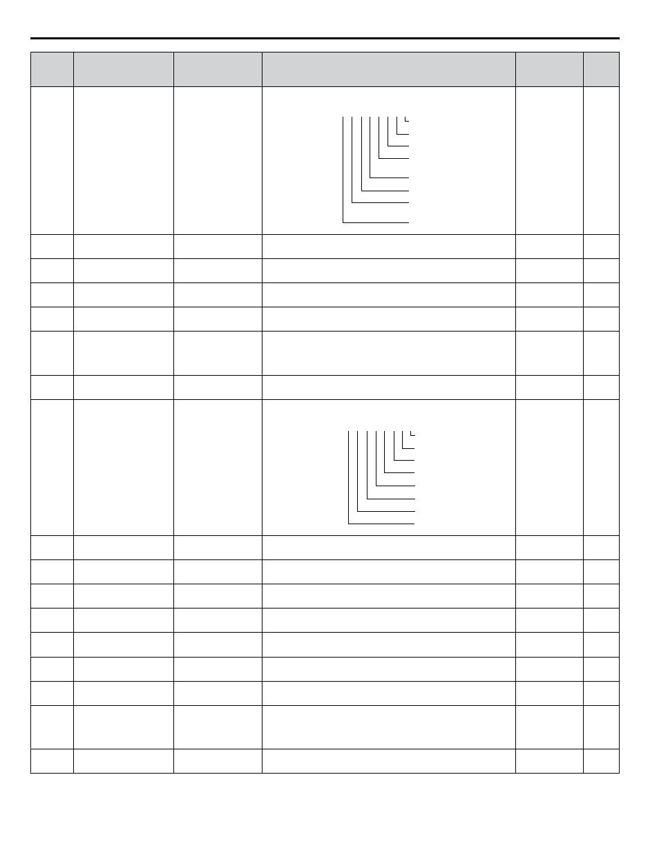
U1-12
(004B) Drive Status
Int Ctl Sts 1
Verifies the drive operation status.
U1 - 12=
00000000
During run
During zero-speed
During REV
During fault reset
signal input
During speed agree
Drive ready
During alarm
detection
During fault detection
1
1
1
1
1
1
1
1
No signal output
available
–
U1-13
(004E) Terminal A1 Input Level Term A1 Level
Displays the signal level to analog input terminal A1.
10 V: 100%
0.1%
U1-14
(004F) Terminal A2 Input Level Term A2 Level
Displays the signal level to analog input terminal A2.
10 V: 100%
0.1%
U1-15
(0050)
Terminal A3 Input Level Term A3 Level
Displays the signal level to analog input terminal A3.
10 V: 100%
(-10 to +10 V)
0.1%
U1-16
(0053)
Output Frequency after
Soft Starter
SFS Output
Displays output frequency with ramp time and S-curves. Units
determined by o1-03.
10 V: Max
frequency
0.01 Hz
U1-17
(0058)
DI-A3 Input Status
DI Opt Status
Displays the reference value input from the DI-A3 option card.
Display will appear in hexadecimal as determined by the digital
card input selection in F3-01.
3FFFF: Set (1 bit) + sign (1 bit) + 16 bit
No signal output
available
–
U1-18
(0061)
oPE Fault Parameter
OPE Error Code
Displays the parameter number that caused the oPEoo or Err
(EEPROM write error) error.
No signal output
available
–
U1-19
(0066)
MEMOBUS/Modbus
Error Code
Transmit Err
Displays the contents of a MEMOBUS/Modbus error.
U1 - 19=
00000000
CRC Error
Data Length Error
Not Used
Parity Error
Overrun Error
Framing Error
Timed Out
Not Used
1
1
0
1
1
1
1
0
No signal output
available
–
U1-21
(0077)
AI-A3 Terminal V1
Input Voltage Monitor
AI Opt Ch1 Level
Displays the input voltage to terminal V1 on analog input card
AI-A3.
10 V: 100%
(-10 to +10 V)
0.1%
U1-22
(072A)
AI-A3 Terminal V2
Input Voltage Monitor
AI Opt Ch2 Level
Displays the input voltage to terminal V2 on analog input card
AI-A3.
10 V: 100%
(-10 to +10 V)
0.1%
U1-23
(072B)
AI-A3 Terminal V3
Input Voltage Monitor
AI Opt Ch3 Level
Displays the input voltage to terminal V3 on analog input card
AI-A3.
10 V: 100%
(-10 to +10 V)
0.1%
U1-25
(004D)
Software Number
(Flash)
CPU 1 SW Number
FLASH ID
No signal output
available
–
U1-26
(005B) Software No. (ROM)
CPU 2 SW Number
ROM ID
No signal output
available
–
U1-27
(07A8) Message ID (OPR)
MessageID(OPR)
OPR ID
No signal output
available
–
U1-28
(07A9) Message ID (INV)
MessageID(DRV)
INV ID
No signal output
available
–
U1-54
(1083)
Drive Input Power
Voltage Effective Value PowerSupply Volt
Displays the effective value of the drive input power voltage.
200 V class
10 V: 400 V
400 V class
10 V: 800 V
1 V
U1-58
(1087)
Power Supply
Frequency
PoweSupply Freq
Displays the frequency of the drive input power supply.
10 V: Rated
frequency
0.1 Hz
B.14 U: Monitors
310
YASKAWA ELECTRIC TOEP C710636 10B Z1000U HVAC MATRIX Drive User Manual