Drive motor overload protection – Yaskawa Z1000U User Manual
Page 355
n
Low Voltage Wiring for Control Circuit Terminals
Wire low voltage wires with NEC Class 1 circuit conductors. Refer to national state or local codes for wiring. The external
power supply shall be a UL listed Class 2 power supply source or equivalent only.
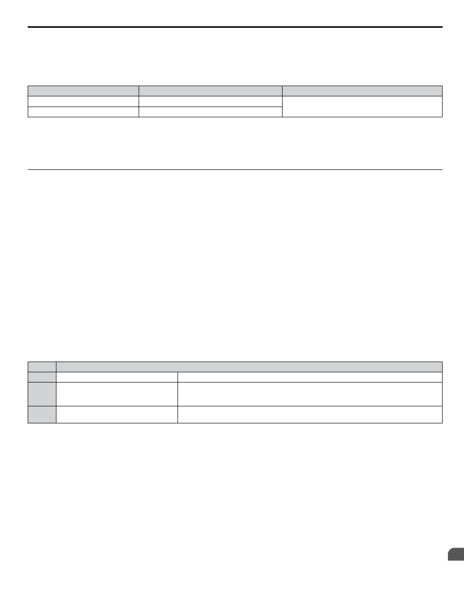
Table D.5 Control Circuit Terminal Power Supply
Input / Output
Terminal Signal
Power Supply Specifications
Multi-function digital inputs
S1 to S8, SC
Use the internal LVLC power supply of the drive or an
external class 2 power supply.
Multi-function analog inputs
+V, A1, A2, A3, AC, FM, AM
n
Drive Short Circuit Rating
The drive is suitable for use on a circuit capable of delivering not more than 100,000 RMS symmetrical amperes, 240 Vac
maximum (200 V class), 480 Vac maximum (400 V class: 4Eoooo and 4Woooo), and 500 Vac maximum (400 V class:
4Uoooo and 4Poooo) with built-in fuses manufactured by Hinode Electric Co., Ltd. and Mersen (or equivalent).
u
Drive Motor Overload Protection
Set parameter E2-01 (motor rated current) to the appropriate value to enable motor overload protection. The internal motor
overload protection is UL Listed and in accordance with the NEC and CEC.
n
E2-01: Motor Rated Current
Setting Range: 10% to 180% of the drive rated current.
Default Setting: Model-dependent
Parameter E2-01 protects the motor when parameter L1-01 is not set to 0. The default for L1-01 is 1, which enables protection
for standard induction motors.
If Auto-Tuning has been performed successfully, the motor data entered to T1-04 and T2-06 are automatically written to
parameter E2-01. If Auto-Tuning has not been performed, manually enter the correct motor rated current to parameter E2-01.
n
L1-01: Motor Overload Protection Selection
The drive has an electronic overload protection function (oL1) based on time, output current, and output frequency that protects
the motor from overheating. The electronic thermal overload function is UL-recognized, so it does not require an external
thermal relay for single motor operation.
This parameter selects the motor overload curve used according to the type of motor applied.
Table D.6 Overload Protection Settings
Setting
Description
0
Disabled
Disabled the internal motor overload protection of the drive.
1
Standard fan-cooled motor
Selects protection characteristics for a standard self-cooled motor with limited cooling capabilities
when running below the rated speed. The motor overload detection level (oL1) is automatically
reduced when running below the motor rated speed.
4
Permanent Magnet motor with variable
torque
Selects protection characteristics for a variable torque PM motor. The motor overload detection
level (oL1) is automatically reduced when running below the motor rated speed.
When connecting the drive to more than one motor for simultaneous operation, disable the electronic overload protection
(L1-01 = 0) and wire each motor with its own motor thermal overload relay.
Enable motor overload protection (L1-01 = 0, 1, or 4) when connecting the drive to a single motor, unless another motor
overload preventing device is installed. The drive electronic thermal overload function causes an oL1 fault, which shuts off
the output of the drive and prevents additional overheating of the motor. The motor temperature is continually calculated while
the drive is powered up.
n
L1-02: Motor Overload Protection Time
Setting Range: 0.1 to 5.0 min
Factory Default: 1.0 min
Parameter L1-02 determines how long the motor is allowed to operate before the oL1 fault occurs when the drive is running
a hot motor at 60 Hz and at 150% of the full load amp rating (E2-01) of the motor. Adjusting the value of L1-02 can shift the
set of oL1 curves up the y axis of the diagram below, but will not change the shape of the curves.
D.3 UL and CSA Standards
YASKAWA ELECTRIC TOEP C710636 10B Z1000U HVAC MATRIX Drive User Manual
355
D
Standards Compliance