H3-01: terminal a1 signal level selection, H3-02: terminal a1 function selection, H3-05: terminal a3 signal level selection – Yaskawa Z1000U User Manual
Page 162: 12 advanced drive setup adjustments
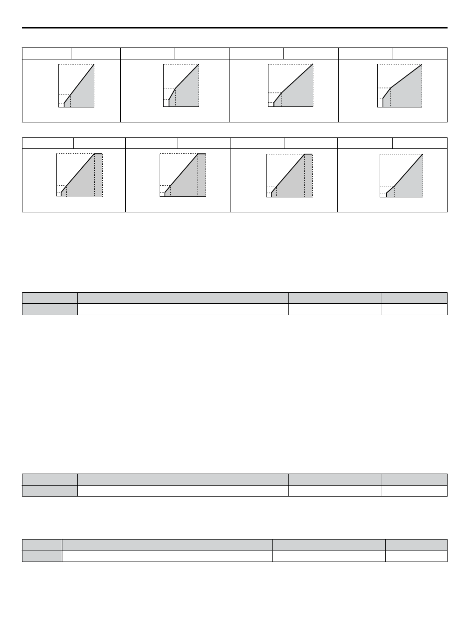
Table 4.37 High Starting Torque, Settings 8 to B
Setting = 8
50 Hz
Setting = 9
50 Hz
Setting = A
60 Hz
Setting = B
60 Hz
0
7
200
1.3 2.5
50
15
V
oltage (V)
Frequency (Hz)
0
9
200
1.3 2.5
50
20
V
oltage (V)
Frequency (Hz)
0
7
200
1.5 3
60
15
V
oltage (V)
Frequency (Hz)
0
11
200
1.5 3
60
20
V
oltage (V)
Frequency (Hz)
Table 4.38 Constant Output, Settings C to F
Setting = C
90 Hz
Setting = D
120 Hz
Setting = E
180 Hz
Setting = F
60 Hz
0
6
12
200
1.5 3
90
60
V
oltage (V)
Frequency (Hz)
0
6
12
200
1.5 3
120
60
V
oltage (V)
Frequency (Hz)
0
6
12
200
1.5 3
180
60
V
oltage (V)
Frequency (Hz)
0
6.9
230
1.5 3
60
13.8
V
oltage (V)
Frequency (Hz)
Setting a Custom V/f Pattern (Setting F: Default)
Setting parameter E1-03 to F allows the user to set up a custom V/f pattern by changing parameters E1-04 to E1-13.
When initialized, the default values for parameters E1-04 to E1-13 will be equal to Predefined V/f pattern 1.
n
H3-01: Terminal A1 Signal Level Selection
Selects the input signal level for analog input A1. Set jumper S1 on the terminal board accordingly for voltage input or current
input.
No.
Name
Setting Range
Default
H3-01
Terminal A1 Signal Level Selection
0 to 3
0
Setting 0: 0 to 10 V with Zero Limit
The input level is 0 to 10 Vdc with zero limit. The minimum input level is limited to 0%, so that a negative input signal due
to gain and bias settings will be read as 0%.
Setting 1: 0 to 10 V without Zero Limit
The input level is 0 to 10 Vdc without zero limit. If the resulting voltage is negative after being adjusted by gain and bias
settings, then the motor will rotate in reverse.
Setting 2: 4 to 20 mA Current Input
The input level is 4 to 20 mA. Negative input values by negative bias or gain settings are limited to 0%.
Setting 3: 0 to 20 mA Current Input
The input level is 0 to 20 mA. Negative input values by negative bias or gain settings are limited to 0%.
n
H3-02: Terminal A1 Function Selection
Selects the input signal level for analog input A1.
Refer to Multi-Function Analog Input Terminal Settings on page 163
instructions on adjusting the signal level.
No.
Name
Setting Range
Default
H3-02
Terminal A1 Function Selection
0 to 26
0
n
H3-05: Terminal A3 Signal Level Selection
Selects the input signal level for analog input A3.
Refer to Multi-Function Analog Input Terminal Settings on page 163
a list of functions and descriptions.
No.
Name
Setting Range
Default
H3-05
Terminal A3 Signal Level Selection
0 to 3
0
4.12 Advanced Drive Setup Adjustments
162
YASKAWA ELECTRIC TOEP C710636 10B Z1000U HVAC MATRIX Drive User Manual