Table 3.6, 8 main circuit wiring – Yaskawa Z1000U User Manual
Page 78
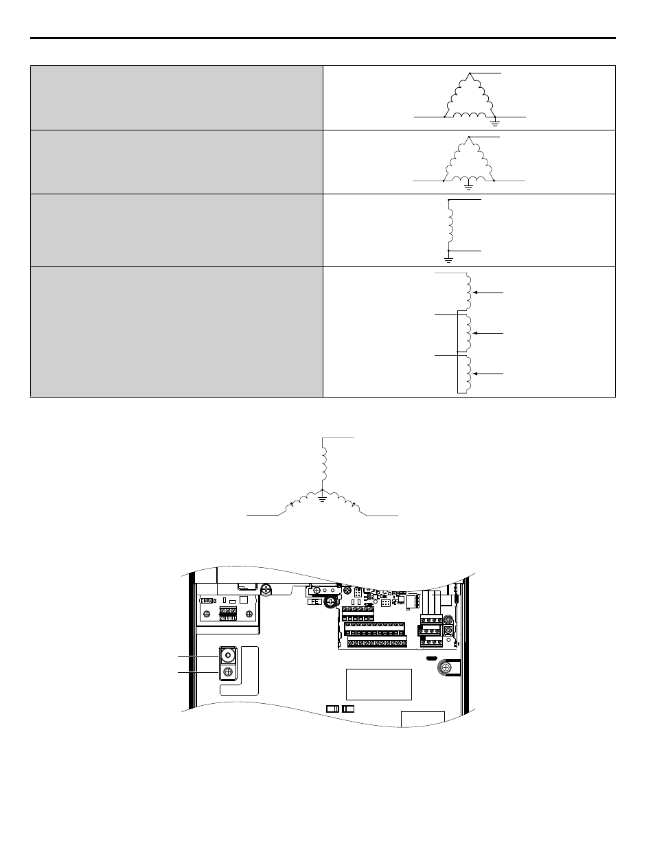
Table 3.6 Asymmetrical Grounded Network
Grounded at the corner of the delta
L1
L2
L3
Grounded at the middle of the side
L1
L2
L3
Single-phase, grounded at the end point
L1
N
Three-phase variable transformer without solidly grounded neutral
L1
L2
L3
L1
L2
L3
If EMC is a concern and the network is grounded symmetrically, install the SW screw to the ON position. Installing the SW
screw enables the internal EMC filter (Drives are shipped with the SW screw installed at the OFF position).
L1
L2
L3
Figure 3.26 Symmetrical Grounded Network
ON
OFF
SW
A
B
E(G) IG R+ R- S+ S-
S1 S2 S3 S4 S5 S6 S7 S8 SN SC SP
V+ AC A1 A2 A3 FM AM AC
24V
RP AC
M1 M2 M3 M4
MD ME MF
MA MB MC
A – SW (ON)
B – Screw (OFF)
Figure 3.27 EMC Filter Switch Location
(Models 2E0028, 2W0028, 4E0011 to 4E0034, and 4W0011 to 4W0034)
3.8 Main Circuit Wiring
78
YASKAWA ELECTRIC TOEP C710636 10B Z1000U HVAC MATRIX Drive User Manual