H2: multi-function digital outputs – Yaskawa Z1000U User Manual
Page 282
u
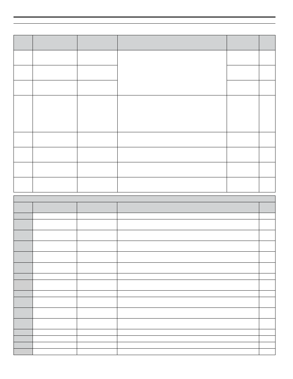
H2: Multi-Function Digital Outputs
No.
(Addr.
Hex)
Name
LCD Display
Description
Values
Page
H2-01
(040B)
Terminal M1-M2
function selection
(relay)
M1-M2 Func Sel
Refer to H2 Multi-Function Digital Output Settings on pages
for descriptions of setting values.
Default: 0
Range: 0 to 1B6
–
H2-02
(040C)
Terminal M3-M4
function selection
(relay)
M3/M4 Func Sel
Default: 1
Range: 0 to 1B6
–
H2-03
(040D)
Terminal MD-ME-MF
function selection
(relay)
MD/ME/MF FuncSel
Default: 2
Range: 0 to 1B6
–
H2-06
(0437)
Power Consumption
Output Unit Selection
Pwr Mon Unit Sel
Sets the units for the output signal when Power Consumption
Pulse Output is selected as the digital output (H2-01, H2-02, or
H2-03 = 39).
0: 0.1 kWh units
1: 1 kWh units
2: 10 kWh units
3: 100 kWh units
4: 1000 kWh units
Default: 1
Range: 0 to 4
–
H2-07
(0B3A)
MEMOBUS Register 1
Address Select
MFDO Regs1 Addr
Sets the addresses of the MEMOBUS/Modbus registers from
which data will be sent to contact outputs 62 and 162.
Default: 1
Range: 1 to
1FFFH
–
H2-08
(0B3B)
MEMOBUS Register 1
Bit Select
MFDO Regs1 Bit
Sets the bits for the MEMOBUS/Modbus registers from which
data will be sent to contact outputs 62 and 162.
Default: 0
Range: 0 to
FFFFH
–
H2-09
(0B3C)
MEMOBUS Register 2
Address Select
MFDO Regs2 Addr
Sets the addresses of the MEMOBUS/Modbus registers from
which data will be sent to contact outputs 63 and 163.
Default: 1
Range: 1 to
1FFFH
–
H2-10
(0B3D)
MEMOBUS Register 2
Bit Select
MFDO Regs2 Bit
Sets the bits for the MEMOBUS/Modbus registers from which
data will be sent to contact outputs 63 and 163.
Default: 0
Range: 0 to
FFFFH
–
H2 Multi-Function Digital Output Settings
H2-oo
Setting
Function
LCD Display
Description
Page
0
During run
During RUN 1
Closed: A Run command is active or voltage is output.
–
1
Zero speed
Zero Speed
Open: Output frequency is above the minimum output frequency set in E1-09.
Closed: Output frequency is below the minimum output frequency set in E1-09.
–
2
Speed agree 1
Fref/Fout Agree1
Closed: Output frequency equals the speed reference (plus or minus the hysteresis
set to L4-02).
–
3
User-set speed agree 1
Fref/Set Agree 1
Closed: Output frequency and speed reference equal L4-01 (plus or minus the
hysteresis set to L4-02).
–
4
Frequency detection 1
Freq Detect 1
Closed: Output frequency is less than or equal to the value in L4-01 with hysteresis
determined by L4-02.
–
5
Frequency detection 2
Freq Detect 2
Closed: Output frequency is greater than or equal to the value in L4-01 with
hysteresis determined by L4-02.
–
6
Drive ready
Drive Ready
Closed: Power up is complete and the drive is ready to accept a Run command.
–
7
During Power Supply
Voltage Fault
DC Bus Undervolt
Closed: The power supply voltage or the control circuit voltage fell below the drive
operating voltage or the power supply frequency is incorrect.
–
8
During baseblock (N.O.) BaseBlk 1
Closed: Drive has entered the baseblock state (no output voltage).
–
9
Frequency reference
source
Ref Source
Open: External Reference 1 or 2 supplies the frequency reference (set in b1-01).
Closed: HOA keypad supplies the frequency reference.
–
A
Run command source
Run Cmd Source
Open: External Reference 1 or 2 supplies the Run command (set in b1-02).
Closed: HOA keypad supplies the Run command.
–
B
Torque detection 1
(N.O.)
Trq Det 1 N.O.
Closed: An overtorque or undertorque situation has been detected.
–
C
Frequency reference loss Loss of Ref
Closed: Analog frequency reference has been lost.
–
E
Fault
Fault
Closed: Fault occurred.
–
F
Through mode
Not Used
Set this value when using the terminal in the pass-through mode.
–
10
Minor Fault
Minor Fault
Closed: An alarm has been triggered.
–
B.8 H Parameters: Multi-Function Terminals
282
YASKAWA ELECTRIC TOEP C710636 10B Z1000U HVAC MATRIX Drive User Manual