Yaskawa Z1000U User Manual
Page 163
Setting 0: 0 to 10 Vdc
The input level is 0 to 10 Vdc. See the explanation provided for H3-01.
Refer to Setting 0: 0 to 10 V with Zero Limit on page
.
Setting 1: -10 to 10 Vdc
The input level is -10 to 10 Vdc. See the explanation provided for H3-01.
Refer to Setting 1: 0 to 10 V without Zero Limit
.
Setting 2: 4 to 20 mA Current Input
The input level is 4 to 20 mA. Negative input values by negative bias or gain settings will be limited to 0%.
Setting 3: 0 to 20 mA Current Input
The input level is 0 to 20 mA. Negative input values by negative bias or gain settings will be limited to 0%.
n
H3-06: Terminal A3 Function Selection
Determines the function assigned to analog input terminal A3.
Refer to Multi-Function Analog Input Terminal Settings on
for a list of functions and descriptions.
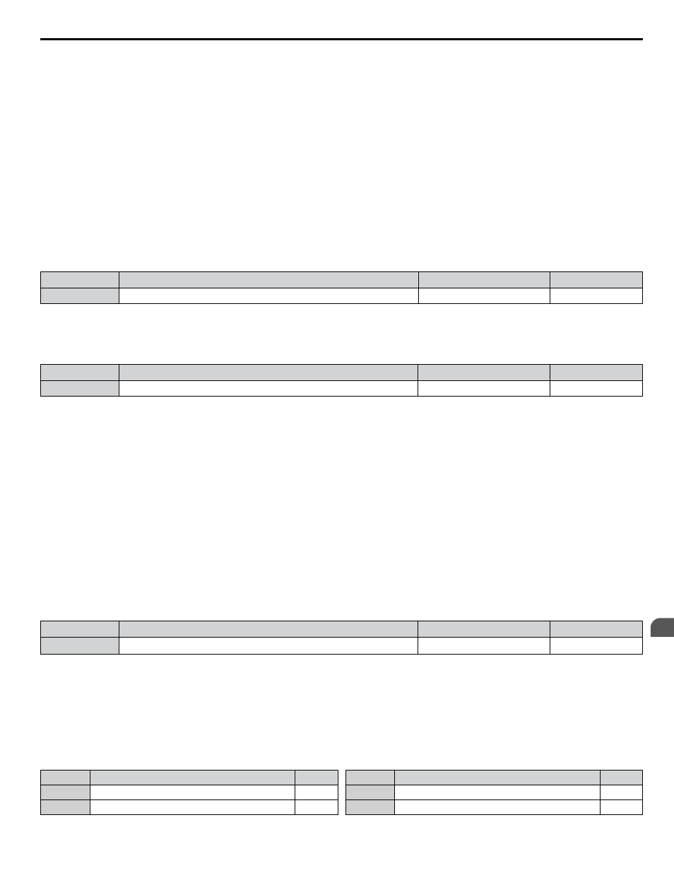
No.
Name
Setting Range
Default
H3-06
Terminal A3 Function Selection
0 to 26
2
n
H3-09: Terminal A2 Signal Level Selection
Selects the input signal level for analog input A2. Set Jumper S1 on the terminal board accordingly for a voltage input or
current input.
No.
Name
Setting Range
Default
H3-09
Terminal A2 Signal Level Selection
0 to 3
2
Setting 0: 0 to 10 V with Zero Limit
The input level is 0 to 10 Vdc. Negative input values will be limited to 0.
Refer to Setting 0: 0 to 10 V with Zero Limit on
Setting 1: 0 to 10 V without Zero Limit
The input level is 0 to 10 Vdc. Negative input values will be accepted.
Refer to Setting 1: 0 to 10 V without Zero Limit on
Setting 2: 4 to 20 mA Current Input
The input level is 4 to 20 mA. Negative input values by negative bias or gain settings will be limited to 0%.
Setting 3: 0 to 20 mA Current Input
The input level is 0 to 20 mA. Negative input values by negative bias or gain settings will be limited to 0%.
n
H3-10: Terminal A2 Function Selection
Determines the function assigned to analog input terminal A2.
Refer to Multi-Function Analog Input Terminal Settings on
for a list of functions and descriptions.
No.
Name
Setting Range
Default
H3-10
Terminal A2 Function Selection
0 to 26
<1>
<1> Default is 0 when b5-01 is set to 0.
Default is B when b5-01 is set to 1 or 3.
n
Multi-Function Analog Input Terminal Settings
for information on how H3-02, H3-10, and H3-06 determine functions for terminals A1, A2, and A3.
Note:
The scaling of all input functions depends on the gain and bias settings for the analog inputs. Set these to appropriate values when selecting
and adjusting analog input functions.
Table 4.39 Multi-Function Analog Input Terminal Settings
Setting
Function
Page
0
Frequency Bias
1
Frequency Gain
Setting
Function
Page
2
Auxiliary Frequency Reference 1
3
Auxiliary Frequency Reference 2
4.12 Advanced Drive Setup Adjustments
YASKAWA ELECTRIC TOEP C710636 10B Z1000U HVAC MATRIX Drive User Manual
163
4
Start-Up Programming & Operation