Altera CPRI IP Core User Manual
Page 67
Chapter 4: Functional Description
4–35
Auxiliary Interface
December 2013
Altera Corporation
CPRI MegaCore Function
User Guide
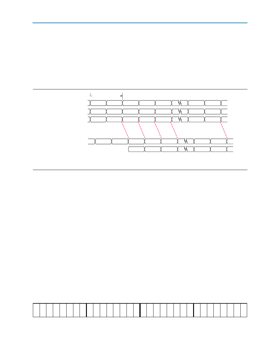
The incoming data on the AUX interface must match the CPRI frame with a delay of
exactly two
cpri_clkout
clock cycles. The
cpri_tx_seq[5:0]
value that you read at
the AUX Tx interface is two
cpri_clkout
cycles ahead of the internal sequence
number that tracks the CPRI frame. If you want your IQ sample to land at sequence
number N of the CPRI frame, then you must present your sample at the AUX Tx
interface when
cpri_tx_seq[5:0]
has the value of N+2.
shows the
expected timing on the incoming AUX connection in a variation with a CPRI line rate
of 6144.4 Mbps.
, the application presents data when
cpri_tx_seq[5:0]
has the value of
4, and sets the value of
cpri_tx_aux_mask
, to ensure the data is loaded in the CPRI
frame immediately following the control word. Because the CPRI line rate in this
example is 6144.4 Mbps, the length of the control word is ten bytes. Therefore, the
application presents the data when
cpri_tx_seq[5:0]
has the value of 4 to ensure the
data is loaded in the CPRI frame at position 2.
In addition, to ensure the CPRI IP core transmits the incoming AUX data correctly on
the CPRI link, you must format the incoming AUX data in the correct order to match
the CPRI IP core internal data representation. If you connect two Altera CPRI IP cores
through a routing layer, and your routing layer does not modify the data transmission
order, then the correct order is guaranteed. However, if a different application
transmits data to the CPRI IP core AUX interface, it must enforce the data order that
the CPRI IP core expects.
Incoming AUX data to the CPRI IP core appears on
cpri_tx_aux_data[31:0]
, also
called
aux_tx_mask_data[64:32]
. Byte [31:24] (64:56]) is transmitted first, and byte
[7:0] (39:32]) is transmitted last:
cpri_tx_aux_data[31:24]
is byte 0 in the
transmission order, and contains the least significant I- and Q-nibbles of the data
sample.
illustrates the required data order on this data bus.
Figure 4–19. Incoming AUX Link Synchronization
Note to
(1) The
cpri_tx_aux_data
and
cpri_tx_aux_mask
signals are fields in the
aux_tx_mask_data
input bus. Refer to
.
cpri_tx_seq[5:0]
internal tx_seq value[5:0]
CPRI Frame
2
1
0
3
4
39
38
36
38
Ctrl
Ctrl
{Ctrl,feed}
0
1
2
37
38
39
cpri_tx_aux_mask[31:0]
cpri_tx_aux_data[31:0]
(1)
(1)
00000000 00000000 00000000
ffffffff
ffffffff
0000ffff
00000000 00000000
00000000
00000000 00000000 0000feed
2
cpri_clkout
cycles
Figure 4–20. Required Data Sample Order in aux_tx_mask_data[63:32] (cpri_tx_aux_data[31:0])
63
56 55
48 47
40 39
32
I[3]
Q[
3]
I[2]
Q[
2]
I[1]
Q[
1]
I[0]
Q[
0]
I[7]
Q[
7]
I[6]
Q[
6]
I[5]
Q[
5]
I[4]
Q[
4]
I[11]
Q[11]
I[10]
Q[10]
I[9]
Q[
9]
I[8]
Q[
8]
I[15]
Q[15]
I[14]
Q[14]
I[13]
Q[13]
I[12]
Q[12]