Altera CPRI IP Core User Manual
Page 124
7–8
Chapter 7: Software Interface
CPRI Protocol Interface Registers
CPRI MegaCore Function
December 2013
Altera Corporation
User Guide
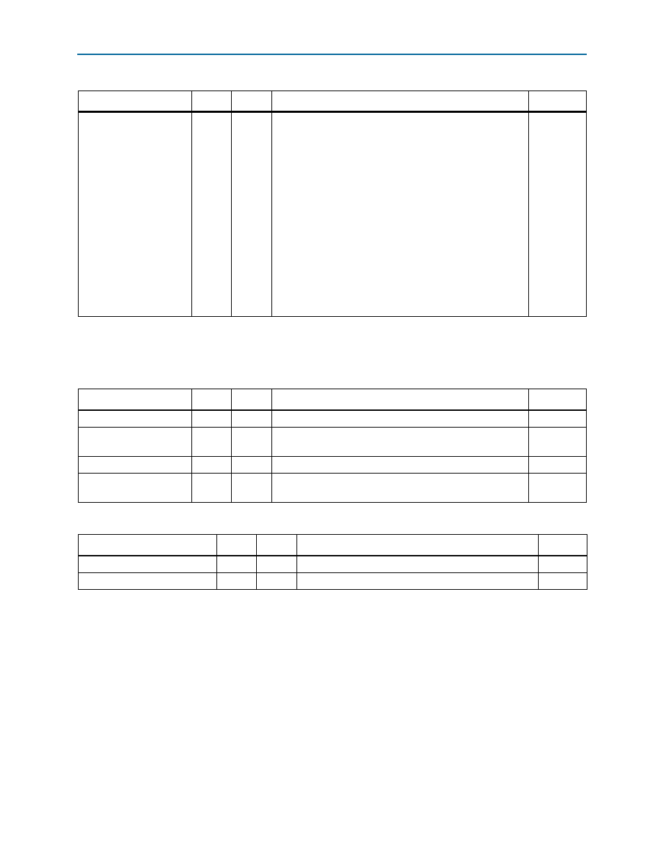
loop_mode
[0]
RW
Physical layer loopback mode. The following values are
defined:
0: No loopback.
1: Full CPRI frame loop. Incoming CPRI data and control
words are sent back as-is in outgoing CPRI
communication. This low-level reverse loopback path is
active whether or not frame synchronization has been
achieved; the path includes 8B/10B encoding and
decoding, but only enough core CPRI functionality to
handle the transition from the receiver clock domain to the
transmitter clock domain.
This loopback mode takes precedence over the 3-bit
loop_mode
specified in the
CPRI_CONFIG
register at offset
0x8: if this field has value 1, the 3-bit
loop_mode
value is
ignored.
2'h0
Note to
:
(1) This register field is a read-to-clear field. You must read the register twice to read the true value of the field after frame synchronization is
achieved. If you observe this bit asserted during link initialization, read the register again after link initialization to confirm any errors.
Table 7–13. CPRI_PHY_LOOP—Physical Layer Loopback Control—Offset: 0x24 (Part 2 of 2)
Field
Bits
Access
Function
Default
Table 7–14. CPRI_CM_CONFIG—CPRI Control and Management Configuration—Offset: 0x28
Field
Bits
Access
Function
Default
RSRV
[31:11] UR0
Reserved.
20'h0
tx_slow_cm_rate
[10:8]
RW
Rate configuration for slow C&M (HDLC). To be inserted in
CPRI control byte Z.66.0.
3’h0
RSRV
[7:6]
UR0
Reserved.
2'h0
tx_fast_cm_ptr
[5:0]
RW
Pointer to first CPRI control word used for fast C&M
(Ethernet). To be inserted in CPRI control byte Z.194.0.
8'h14
Table 7–15. CPRI_CM_STATUS—CPRI Control and Management Status—Offset: 0x2C (Part 1 of 2)
Field
Bits
Access
Function
Default
RSRV
[31:12] UR0
Reserved.
20’h0
rx_slow_cm_rate_valid
[11]
RO
Indicates that a valid slow C&M rate has been accepted.
1'h0